Installation Instructions RDD-Series Rotary Direct Drive Bearingless Motors Catalog Numbers RDB-B2901, RDB-B2902, RDB-B2903, RDB-B4101, RDB-B4102, RDB-B4103 Topic Page Important User Information 2 Catalog Number Explanation 3 Before You Begin 4 Install the Motor 9 Remove the Motor 20 Connector Data 27 Product Dimensions 28 Connector Information 31 Specifications 31 Additional Resources 32 About the Direct Drive Bearingless Motors RDD-Series direct drive motors feature single-turn or
RDD-Series Rotary Direct Drive Bearingless Motor Installation Instructions Important User Information Solid state equipment has operational characteristics differing from those of electromechanical equipment. Safety Guidelines for the Application, Installation and Maintenance of Solid State Controls, publication SGI-1.1, is available from your local Rockwell Automation sales office or online at http://literature.rockwellautomation.
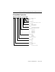
RDD-Series Rotary Direct Drive Bearingless Motor Installation Instructions 3 Catalog Number Explanation RD B - B 410 3 F - 7 B 7 2 AA FACTORY DESIGNATED OPTIONS AA = Standard BRAKE 2 = No Brake CONNECTORS 7 = Circular, Right Angle, Feedback 180° Rotatable ENCLOSURE/SHAFT B = IP65 Housing/Blind Bore T = IP64 Housing/Thru Bore FEEDBACK 3 = Single-turn High Resolution Heidenhain 7 = Multi-turn High Resolution Heidenhain BASE SPEED 4 = 200 rpm @ 440V 5 = 250 rpm @ 440V 6 = 375 rpm @ 440V
RDD-Series Rotary Direct Drive Bearingless Motor Installation Instructions Before You Begin Remove all packing material, wedges, and braces from within and around the item. After unpacking, verify the nameplate catalog number against the purchase order. 1. Remove the motor carefully from its shipping container. 2. Visually inspect the motor frame, mounting pilot, and connectors for damage. 3. Notify the carrier of any shipping damage immediately. 4.
RDD-Series Rotary Direct Drive Bearingless Motor Installation Instructions 5 Required Tools These tools are needed to install this product. Tools Required for Installation Value Hex bit, 150 mm (6 in.) minimum length 6 mm Torque wrench Capable of applying at least 65 N•m (50 lb•ft) Screwdriver Phillips #2 Micrometer N/A Straight edge Caliper Runout indicator Cleaning cloth Shaft key (provided) These additional tools are needed to remove this product.
RDD-Series Rotary Direct Drive Bearingless Motor Installation Instructions Prolonging Motor Life Thoughtful design and proper maintenance can increase the life of this motor. Follow these guidelines to maximize the life of the motor: • Always provide a drip loop in each cable to carry liquids away from the connection to the motor. • If design requirements permit, provide shields that protect the motor housing, shaft, seals, and their junctions from contamination by foreign matter or fluids.
RDD-Series Rotary Direct Drive Bearingless Motor Installation Instructions 7 Build and Route Cables Knowledgeable cable routing and careful cable construction improves system performance. Follow these guidelines to build and install cables: • Keep wire lengths as short as physically possible. • Route noise sensitive wiring (encoder, serial, I/O) away from input power and motor power wiring. • Separate cables by 0.3 m (1 ft) minimum for every 9 m (30 ft) of parallel run.
RDD-Series Rotary Direct Drive Bearingless Motor Installation Instructions Ground the Shielded Signal Wires within a Power Cable Always ground the shield on any signal wires inside a power cable. Connecting this shield to chassis ground reduces the potential for voltage inductance and EMI. SHOCK HAZARD If any shield on a power cable is not grounded, high voltage can be present on that shield.
RDD-Series Rotary Direct Drive Bearingless Motor Installation Instructions 9 Install the Motor All motors include a mounting pilot for aligning the motor on the machine. Preferred fasteners are hardened steel. The installation must comply with all local regulations and use equipment and installation practices that promote safety and electromagnetic compatibility. ATTENTION Unmounted motors, disconnected mechanical couplings, loose shaft keys, and disconnected cables are dangerous if power is applied.
RDD-Series Rotary Direct Drive Bearingless Motor Installation Instructions Preparing the Motor for Installation Follow these steps to prepare a motor for installation. 1. Verify sufficient clearance, heatsink mass, and air flow for the motor so it stays within the operating temperature range of 0…40 °C (32…104 °F). Do not enclose the motor unless cooling air is forced across the motor, and keep other heat producing devices away from the motor.
RDD-Series Rotary Direct Drive Bearingless Motor Installation Instructions 11 Verify Machine Mounting Dimensions Verify proper fit of the motor to the machine mount by measuring the following machine mounting dimensions: 1. Verify these dimensions are within the measurement range in the tables: • Pilot diameter • Shaft diameter, large and small • Shaft length, small and overall 2.
RDD-Series Rotary Direct Drive Bearingless Motor Installation Instructions RDB-B2901, RDB-B2902, RDB-B2903 Machine Mounting Dimensions Attribute Value Pilot diameter 232.92…232.96 mm (9.170…9.172 in.) Shaft diameter, small 59.988…59.999 mm (2.3617…2.3622 in.) Shaft diameter, large 69.988…69.999 mm (2.7554…2.7559 in.) Shaft length, small RDB-B2901 RDB-B2902 RDB-B2903 43.81…44.07 mm (1.725…1.735 in.) 88.01…88.27 mm (3.465…3.475 in.) 124.58…124.84 mm (4.905…4.915 in.
RDD-Series Rotary Direct Drive Bearingless Motor Installation Instructions 13 Mount the Motor Follow these steps to install a motor on the machine. 1. Insert the shaft key (provided) into the keyway of the machine shaft. Position the point on the shaft key in the direction of the motor, and then fully seat the key in the slot.
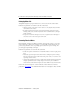
RDD-Series Rotary Direct Drive Bearingless Motor Installation Instructions Remove the End Cover Loosen each pan head screw with a Phillips screwdriver. • The RDB-x290x motor (shown) has eight (8) screws to loosen. • The RDB-x410x motor has eleven (11) screws to loosen. IMPORTANT Do not attempt to remove the pan head screws from the cover. The screws are attached to the end cover with a mechanical lock-ring.
RDD-Series Rotary Direct Drive Bearingless Motor Installation Instructions 15 Tighten the Compression Coupling Follow these steps to secure the motor on the machine shaft. 1. Access the compression coupling bolts through the holes labeled A. • The RDB-x290x motor has six (6) bolts to tighten. • The RDB-x410x motor has ten (10) bolts to tighten. Refer to the following figures for bolt hole locations. 2.
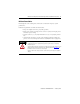
RDD-Series Rotary Direct Drive Bearingless Motor Installation Instructions Mounting Bolts Locations RDB-x290x with Rear Cover Removed C B A C A B A A B A C A B C RDB-x410x with Rear Cover Removed (RDB-x4103 is shown) B A C A A A A A B A A A C B Publication RDB-IN002B-EN-P — February 2010 D A B D C C
RDD-Series Rotary Direct Drive Bearingless Motor Installation Instructions 17 Remove and Secure the Shipping Hardware Follow these steps to remove the shipping bolts and set screws that prevent rotor movement during shipping. 1. Remove the shipping bolt from each hole B using a 6 mm hex bit, and store each bolt in the foam holder. There are four (4) shipping bolts total. Refer to the diagram on page 15 for the location of each hole B. 2.
RDD-Series Rotary Direct Drive Bearingless Motor Installation Instructions Attach Motor Cables Follow these steps to attach the feedback and power/brake cables after the motor is mounted. ATTENTION Make sure that cables are installed and restrained to prevent uneven tension or flexing at the motor-to-cable connections. Excessive and uneven lateral force at the motor connectors can result in the connector’s environmental seal opening and closing as the cable flexes.
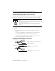
RDD-Series Rotary Direct Drive Bearingless Motor Installation Instructions 19 3. Carefully align the flat surface on the feedback or power/brake cable plug with the flat surface on the motor connector. IMPORTANT The connector orientation shown is used to clearly show the alignment marker on each cable socket. The recommended orientation when installed positions the connectors at the bottom of the motor. 4. Hand-tighten the collar on the plug to fully seat it on the connector.
RDD-Series Rotary Direct Drive Bearingless Motor Installation Instructions Remove the Motor Remove the motor from a machine as outlined below. BURN HAZARD Outer surfaces of a motor can reach high temperatures, 125 °C (275 °F), during operation. Take precautions to prevent accidental contact with hot surfaces. Consider motor surface temperature when selecting connections and cables to install on a motor. Failure to observe safety precautions could result in personal injury or damage to equipment.
RDD-Series Rotary Direct Drive Bearingless Motor Installation Instructions 21 Align the Rotor Follow these steps to align the rotor prior to removing the motor. 1. Use a flashlight to illuminate all holes (A, B and C) in the housing. To locate the holes, refer to the diagrams on page 15. 2. Turn the shaft by hand until a threaded hole directly aligns with each hole B, and the hex bolts on the compression coupling are visible through each hole A. 3. Verify each hole C shows the flat surface of the rotor.
RDD-Series Rotary Direct Drive Bearingless Motor Installation Instructions Install the Set Screws and Shipping Bolts Follow these steps to install the set screws that prevent rotor movement during shipping. ATTENTION Do not use a thread lock material on the shipping bolts. 1. Remove each set screw from the foam holder, and insert it in a hole C. There are four (4) set screws total. Refer to the diagram on page 15 for the locations. 2. Tighten each set screw to 0.1 N•m (1 lb•in.
RDD-Series Rotary Direct Drive Bearingless Motor Installation Instructions 23 Loosen the Compression Coupling Bolts Follow these steps to loosen the compression coupling bolts prior to releasing the compression coupling from the shaft. 1. Access the compression coupling bolts through the holes labelled A. • The RDB-x290x motor has six (6) compression bolts to loosen. • The RDB-x410x motor has ten (10) compression bolts to loosen. Refer to the diagram on page 15 for the locations. 2.
RDD-Series Rotary Direct Drive Bearingless Motor Installation Instructions Release the Compression Coupling Follow these steps to loosen the respective motor from a machine shaft. TIP The RDB-x4103 motor has a two-stage compression coupling. Release the first and second stages by performing both steps below, starting with the initial step that is common for all RDB-x290x or RDB-x410x motors. RDB-x290x and RDB-x410x Motors 1. Seat a 6 mm hex driver on the compression coupling bolt.
RDD-Series Rotary Direct Drive Bearingless Motor Installation Instructions 25 Replace the End Cover Follow these steps to align and secure the end cover in its original position. 1. Verify the O-ring is in position on the outside of the end cover. 2. Rotate the end cover so the alignment mark on the cover aligns with the corresponding mark on the motor housing. 3. Tighten each pan head screw to secure the end cover on the motor. • The RDB-x290x motor has eight (8) screws to tighten.
RDD-Series Rotary Direct Drive Bearingless Motor Installation Instructions Cover the Mounting End of the Motor Seal the opening in the motor end by performing the following steps. 1. Insert the protective paper sleeving around the rotor. 2. Cover the opening at the mounting end of the motor with the cardboard cover that came with the motor. ATTENTION The motor contains strong magnets that can attract metallic materials. Accidental entry of foreign material can harm motor performance.
RDD-Series Rotary Direct Drive Bearingless Motor Installation Instructions 27 Connector Data These tables identify the pinouts for feedback and power connectors.
RDD-Series Rotary Direct Drive Bearingless Motor Installation Instructions Product Dimensions EB T E G GD D N F Key DB LA LD Key supplied with motor. Orient as shown. LE LB R P AD HD S = Dia. of Bolt Holes M = Dia. of Bolt Circle The dimensions in the table are for motors with a single-turn or a multi-turn encoder. Footnotes identify tolerances and dimensional differences.
RDD-Series Rotary Direct Drive Bearingless Motor Installation Instructions 29 Motor Dimensions Dimension mm (in.) Motor Cat. No. RDB-B2901 RDB-B2902 RDB-B2903 RDB-B4101 RDB-B4102 AD Max (1) 182.3 (7.18) 256.3 (10.09) D 59.988… 59.999 (2.3617… 2.3622) 69.988…69.999 (2.7554…2.7559) 69.988…69.999 (2.7554…2.7559) 79.988…79.999 (3.1491…3.1496) DB RDB-B4103 43.94 (1.730) 88.14 (3.470) 124.71 (4.910) 40.39 (1.590) 83.82 (3.300) 118.62 (4.670) EB 89.92 (3.540) 134.11 (5.280) 170.69 (6.
RDD-Series Rotary Direct Drive Bearingless Motor Installation Instructions Motor Dimensions (cont.) Dimension mm (in.) Motor Catalog No. P 245.9 (9.68) 350.0 (13.78) R 16.8 (0.66) 38.6 (1.52) S 14.0 (0.551) 17.5 (0.689) 13.5 (0.53) 17.8 (0.
RDD-Series Rotary Direct Drive Bearingless Motor Installation Instructions 31 Specifications Attribute Value Ambient temperature, operating 0…40 °C (32…104 °F) (2) Ambient temperature, storage -30…70 °C (-22…158 °F) Relative humidity, storage 5…95% noncondensing Atmosphere, storage Non-corrosive IP rating (1) IP65 - dust tight, water jet (3) (1) The motor rating excludes any reduction in the rating resulting from cables, plugs, or connections with a lower rating, and an unsealed customer mac
Additional Resources These documents contain additional information concerning related Rockwell Automation products. Resource Description Kinetix 6000 Multi-axis Servo Drives User Manual, publication 2094-UM001 Information on installing, configuring, starting up, and troubleshooting for your Kinetix 6000 servo drive system.