Installation Instructions RDD-Series Rotary Direct Drive Bearingless Motors Catalog Numbers RDB-B2151, RDB-B2152, RDB-B2153 Topic Page Important User Information 2 Catalog Number Explanation 3 Before You Begin 4 Install the Motor 8 Remove the Motor 16 Connector Data 18 Product Dimensions 19 Connector Information 21 Specifications 21 Additional Resources 22 About the Rotary Direct Drive Bearingless Motors RDD-Series direct drive motors feature single-turn or multi-turn high resolution
RDD-Series Rotary Direct Drive Bearingless Motor Installation Instructions Important User Information Solid state equipment has operational characteristics differing from those of electromechanical equipment. Safety Guidelines for the Application, Installation and Maintenance of Solid State Controls, publication SGI-1.1, is available from your local Rockwell Automation sales office or online at http://literature.rockwellautomation.
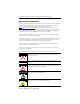
RDD-Series Rotary Direct Drive Bearingless Motor Installation Instructions 3 Catalog Number Explanation RD B - B 215 3 C - 7 B 7 2 AA FACTORY DESIGNATED OPTIONS AA = Standard BRAKE 2 = No Brake CONNECTORS 7 = Circular, Right Angle, 180° Rotatable ENCLOSURE/SHAFT B = IP65 Housing/Blind Bore FEEDBACK 3 = Single-turn High Resolution Heidenhain 7 = Multi-turn High Resolution Heidenhain BASE SPEED 9 = 750 rpm @ 440V C = 1000 rpm @ 440V MAGNET STACKS 1 = One Stack 2 = Two Stacks 3 = Three
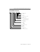
RDD-Series Rotary Direct Drive Bearingless Motor Installation Instructions Before You Begin Remove all packing material, wedges, and braces from within and around the item. After unpacking, verify the nameplate catalog number against the purchase order. 1. Remove the motor carefully from its shipping container. 2. Visually inspect the motor frame, mounting pilot, and connectors for damage. 3. Notify the carrier of any shipping damage immediately. 4.
RDD-Series Rotary Direct Drive Bearingless Motor Installation Instructions 5 Prolonging Motor Life Thoughtful design and proper maintenance can increase the life of this motor. Follow these guidelines to maximize the life of the motor: • Always provide a drip loop in each cable to carry liquids away from the connection to the motor. • If design requirements permit, provide shields that protect the motor housing, shaft bore, seals, and their junctions from contamination by foreign matter or fluids.
RDD-Series Rotary Direct Drive Bearingless Motor Installation Instructions Build and Route Cables Knowledgeable cable routing and careful cable construction improves system performance. Follow these guidelines to build and install cables: • Keep wire lengths as short as physically possible. • Route noise sensitive wiring (encoder, serial, I/O) away from input power and motor power wiring. • Separate cables by 0.3 m (1 ft) minimum for every 9 m (30 ft) of parallel run.
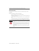
RDD-Series Rotary Direct Drive Bearingless Motor Installation Instructions 7 Ground the Shielded Signal Wires within a Power Cable Always ground the shield on any signal wires inside a power cable. Connecting this shield to chassis ground reduces the potential for voltage inductance and EMI. SHOCK HAZARD If any shield on a power cable is not grounded, high voltage can be present on that shield.
RDD-Series Rotary Direct Drive Bearingless Motor Installation Instructions Install the Motor All motors include a mounting pilot for aligning the motor on the machine. Preferred fasteners are hardened steel. The installation must comply with all local regulations and use equipment and installation practices that promote safety and electromagnetic compatibility. ATTENTION Unmounted motors, disconnected mechanical couplings, loose shaft keys, and disconnected cables are dangerous if power is applied.
RDD-Series Rotary Direct Drive Bearingless Motor Installation Instructions 9 Prepare the Motor for Installation Follow these steps to prepare a motor for installation. 1. Verify sufficient clearance, heatsink mass, and air flow for the motor so it stays within the operating temperature range of 0…40 °C (32…104 °F). Do not enclose the motor unless cooling air is forced across the motor, and keep other heat producing devices away from the motor.
RDD-Series Rotary Direct Drive Bearingless Motor Installation Instructions Verify Machine Mounting Dimensions Verify proper fit of the motor to the machine mount by measuring the following machine mounting dimensions. 1. Verify these dimensions are within the measurement range in the table: • Pilot diameter • Shaft diameter, small and large • Shaft length, small and overall 2.
RDD-Series Rotary Direct Drive Bearingless Motor Installation Instructions 11 RDB-B2151, RDB-B2152, RDB-B2153 Machine Mounting Dimensions Attribute Value Pilot diameter 163.989…164.014 mm (6.4563…6.4372 in.) Shaft diameter, small 70.985…71.000 mm (2.7947…2.7953 in.) Shaft diameter, large 71.985…72.000 mm (2.8340…2.8346 in.) Shaft length, small RDB-B2151 RDB-B2152 RDB-B2153 48.60…49.40 mm (1.915…1.945 in.) 82.60…83.40 mm (3.255…3.285 in.) 116.60…117.40 mm (4.595…4.625 in.
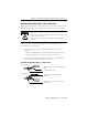
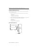
RDD-Series Rotary Direct Drive Bearingless Motor Installation Instructions Mount the Motor Follow the diagram and steps below to install a motor on the machine. IMPORTANT The preferred motor-mounting orientation is with the feedback and power connectors on the bottom of the motor. The preferred orientation improves environmental protection. Alternate alignment ports are shown in the Product Dimensions drawing. 1 2 3 Step Description 1 Center motor on shaft.
RDD-Series Rotary Direct Drive Bearingless Motor Installation Instructions 13 Tighten the Compression Coupling Follow these steps to secure the motor on the machine shaft. 1. Remove the black cap screw from the hole A using a Phillips #4 screwdriver. Refer to the motor outline on page 19 for the location of the compression coupling fitting and alignment pin. 2. Use a 6 mm hex bit to tighten the compression coupling in hole A to 29.8 N•m (22 lb•ft).
RDD-Series Rotary Direct Drive Bearingless Motor Installation Instructions Attach the Motor Cables Follow these steps to attach the feedback and power/brake cables after the motor is mounted. Make sure that cables are installed and restrained to prevent uneven tension or flexing at the motor-to-cable connections. ATTENTION Excessive and uneven lateral force at the motor connectors can result in the connector’s environmental seal opening and closing as the cable flexes.
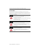
RDD-Series Rotary Direct Drive Bearingless Motor Installation Instructions 15 3. Carefully align the flat surface on the feedback or power/brake cable plug with the flat surface on the motor connector. The connector orientation shown is used to clearly show the alignment marker on each cable socket. IMPORTANT The recommended orientation when installed positions the connectors at the bottom of the motor. 4. Hand tighten the collar on the plug to fully seat it on the connector.
RDD-Series Rotary Direct Drive Bearingless Motor Installation Instructions Remove the Motor Follow these steps to remove a motor from a machine. Outer surfaces of a motor can reach high temperatures, 125 °C (275 °F), during operation. BURN HAZARD Take precautions to prevent accidental contact with hot surfaces. Consider motor surface temperature when selecting connections and cables to install on a motor. Failure to observe safety precautions could result in personal injury or damage to equipment.
RDD-Series Rotary Direct Drive Bearingless Motor Installation Instructions 17 Release the Compression Coupling Follow these steps to release the compression coupling prior to dismounting the motor. 1. Use a 6 mm hex bit to loosen the compression coupling in hole A. 2. Loosen the compression coupling one complete revolution beyond finger-tight to be sure the coupling releases from the machine shaft. 3. Secure the black cap screw in hole A by tightening it to 3.4 N•m (2.5 ft•lb).
RDD-Series Rotary Direct Drive Bearingless Motor Installation Instructions Connector Data These tables identify the pinouts for feedback and power connectors.
RDD-Series Rotary Direct Drive Bearingless Motor Installation Instructions 19 Product Dimensions P LB 104.4 (4.11) T HD AD LA LE RDB-B215x with Connector Size: M23 Fdbk and M23 Pwr (shown) = 73.1 mm (2.88 in.) M23 Fdbk and M40 Pwr (not shown) = 81.9 mm (3.22 in.) LD EB E NB B A Shipping Alignment Pin Coupling Access Port with Cap Screw Cover Location of Alternate Coupling Access Port and Shipping Alignment Pin D DB TB Customer Interface Detail of Machine Mounting Shaft S = Dia.
RDD-Series Rotary Direct Drive Bearingless Motor Installation Instructions Bearingless Motor Dimensions Cat No. RDB- AD Max (1) mm (in.) D mm (in.) DB Max mm (in.) E (2) mm (in.) EB (3) mm (in.) HD (1) mm (in.) LA mm (in.) LB (4) mm (in.) LD (5) mm (in.) B2151 136.7 (5.38) 70.985… 71.0 (2.7947… 2.7953) 71.985… 72.0 (2.8340… 2.8346) 49.0 (1.93) 104.0 (4.09) 230.9 (9.09) 14.0 (0.55) 226.05 (8.90) 165.70 (6.524) 83.0 (3.27) 138.0 (5.43) 260.05 (10.24) 199.70 (7.862) 117.1 (4.
RDD-Series Rotary Direct Drive Bearingless Motor Installation Instructions 21 Connector Information Connector information includes the manufacturer part numbers for connector shells, and contacts for power, ground, and feedback pins. Connector Mount Type Connector Shell (1) Power and Ground Contacts Feedback Contacts Feedback, M23 90 degree swivel mount AEDC113NN00000200000 N/A 61.004.11 BEDC091NN000200000 61.193.11 N/A CEDE271NN00000051000 61.203.
RDD-Series Rotary Direct Drive Bearingless Motor Installation Instructions Additional Resources These documents contain additional information concerning related Rockwell Automation products. Resource Description Kinetix 6000 Multi-axis Servo Drives User Manual, publication 2094-UM001 Information on installing, configuring, starting up, and troubleshooting for your Kinetix 6000 servo drive system.
RDD-Series Rotary Direct Drive Bearingless Motor Installation Instructions 23 Notes: Publication RDB-IN001A-EN-P — October 2009
Rockwell Automation Support Rockwell Automation provides technical information on the Web to assist you in using its products. At http://support.rockwellautomation.com, you can find technical manuals, a knowledge base of FAQs, technical and application notes, sample code and links to software service packs, and a MySupport feature that you can customize to make the best use of these tools.