
User Manual Owner's manual


1 Publication 1757-UM006A-EN-P - May 2002
Chapter
7
Using the 1788-CN2FF,
ControlNet-to-FOUNDATION Fieldbus H1
Linking Device
This chapter describes:
• the blocks in the linking device
• configuring the linking device to access the AI, AO, DI, DO
function blocks on the Fieldbus network from ControlNet
• attributes of the created ControlNet objects, assembly objects,
alarm handling
• ControlNet connection details
Blocks in the Linking
Device
The linking device is similar to an I/O subsystem. An I/O subsystem
typically contains several I/O modules. Each module has a number of
channels. The channels perform either analog input, analog output,
discrete input, or discrete output functions. The linking device models
the I/O modules in software. The linking device has four types of
function blocks:
• Multiple Analog Input (MAI)
• Multiple Analog Output (MAO)
• Multiple Discrete Input (MDI)
• Multiple Discrete Output (MDO)
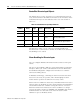
Each of these function blocks has eight channels. Each channel is a
combination of a value and Fieldbus status.
You can connect an analog input function block on the Fieldbus
network to a channel on the MAI block, just as you would wire a
4-20ma analog input to an analog channel in your I/O subsystem. The
main difference is that the Fieldbus function blocks do considerable
processing. The channel value represents a scaled value in
engineering units. Each value has an associated status. The status is
more than a boolean of good or bad. It has four major status values of
Good or Bad, with 16 sub-status values for each major status, and four
limits.