
User Manual Owner's manual


Publication 1757-UM006A-EN-P - May 2002
6-6 1757-FIM General Maintenance, Checkout, and Calibration
Checking Fieldbus Device
Calibration
Please refer to the manufacturer’s documentation for the fieldbus
device to determine the recommended calibration schedules and
procedures. The Other tab on the Parameters form for a device’s
transducer block provides pertinent calibration information, when
accessed through the Monitoring tab in Control Builder.
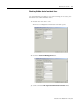
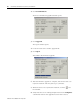
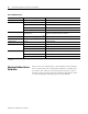
Table 6.A LED Definitions
If Module Health LED is: And, 4-Character Display shows: The FIM is:
Flashing Red/Green TEST Running its self-test.
Flashing Green/Off BOOT Initiating its startup or boot sequence.
ALIV in its ALIVE state and ready for its Personality Image load.
LOAD In the midst of a firmware load sequence.
RDY In its READY state and ready for its Boot image load.
Solid or Flashing Green Alternating link states as noted in the
following rows.
Operating normally. If solid green, there are ProcessLogix Control
Data Access (CDA) connections to the FIM.
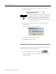
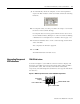
If Link 1 or Link 2 LED is:
And, 4-Character Display shows:
(1)
Then, LINK is:
Off or Flashing Red X- - - Down/offline.
Flashing Green X – FW Loading firmware.
Flashing Red X – FE Having a firmware load error.
X – CE Having a communications initialization error.
X – DE Having a database initialization error.
Flashing Green or Off X – CI Initializing communications with fieldbus devices.
X – DI Initializing database.
X – YY Communicating with fieldbus devices.
(1)
Display alternates between Link 1 and Link 2 in two second intervals. The X is either 1 or 2 for the respective Link and YY equals the number of fieldbus devices present on a
given Link.