
User manual


Publication 1760-UM001D-EN-P - September 2005
A-12 Specifications
Inductive Load (without external suppression)
An unsuppressed inductive load applies stresses to the transistor
output when the load is switched off. It is recommended that all
inductive loads be suppressed. To reduce the risk of damage,
deratings should be applied to the transistor outputs if inductive loads
are not suppressed.
The outputs of the 1760-IB12XOB8 are internally connected in two
groups, S1 to S4 and S5 to S8. No more than one unsuppressed load
should be operated in each output group. The unsuppressed load
should be switched no more frequently than 0.5 Hz (once every two
seconds).
Reverse Polarity Protection Yes
CAUTION: If voltage is applied to the outputs when the polarity of the power supply is
reversed, this will result in a short circuit.
Isolation from Power Supply and Input
Terminals
500V dc
Rated Current 0.5 A dc maximum
Lamp Load 5 W
Off State Leakage Current < 0.1 mA per channel
Maximum Output Voltage Drop 1V dc
Short Circuit Protection Yes, thermal (detected via diagnostics input I16, I15; R15, R16)
Short Circuit Tripping Current, I
for Load ≤ 10 milli-ohm
0.7 A ≤ I ≤ 2 A (depending on the number of active channels and their load)
Short Circuit Current 8 A total maximum 16 A total maximum
16 A peak 32 A peak
Thermal Cutout Yes
Maximum Switching Frequency with
Constant Resistive Load RL < 100 kΩ
40,000 Hz (depending on circuit diagram and load)
Parallel Connection of Outputs with
Resistive Load; Inductive Load with
External Suppression Circuit Combination
Within a Group (see page 2-25)
Group 1: Q1 to Q4, S1 to S4 Group 1: Q1 to Q4, S1 to S4
Group 2: Q5 to Q8, S5 to S8
Number of Outputs 4 maximum
Total Maximum Current 2.0 A
CAUTION: Outputs must be actuated simultaneously and for the same time duration.
Status Display of the Outputs LCD display (if provided)
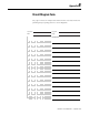
Specification 1760-L12BBB
1760-L12BBB-ND
1760-IB12XOB8
1760-L20BBB-EX
1760-L20BBB-EXND