
User manual


Publication 1760-UM001D-EN-P - September 2005
Retention 7-13
Flashing Switch Operation, Retentive
Task:
A flasher function is used to lower an ink stamp at identical time
intervals to print an area and then to raise the stamp to prepare for the
next hit.
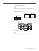
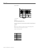
Contacts and relays used:
Signal diagram:
U = Supply voltage
Range A:
Within this range, the power is turned off. Following another
power-on, the remaining time runs until finished.
Coil Function
Q1 Valve
T8 Time
10.00
TRG
RES
T8
+
{
S
-----------TT8
T8---------{Q1
Parameters entered:
Circuit Diagram:
T8
Q1
U
tt
1
t
2
t
A
t
+
t = t
12