
User Manual

Rockwell Automation Publication 20B-IN025B-EN-P - January 2011 63
Component Replacement Procedures Chapter 3
Install Components
1. Using isopropyl alcohol, thoroughly clean the Heatsink mounting surface
where each new SCR module will be installed.
2. Verify that the mounting surface of each new SCR module is clean. If not,
clean with isopropyl alcohol.
3. Using a 3- or 4-inch paint roller or putty knife, apply a thin, even coating of
the supplied thermal grease to the mounting surface of each new SCR
module.
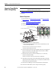
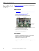
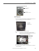
4. Install each new SCR module with supplied screws and tighten using this
torque sequence:
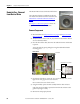
5. Replace the SCR module leads.
Each set of leads is marked R, S, or T. The notch and red wire on each lead
are positioned to the front.
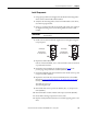
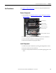
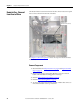
6. Install the Converter Busbars per the illustration and step 6
on the
previous page. Torque all bolts to 9.0 N•m (80 lb•in).
7. Install the Snubber Boards, oriented with the serial number at the top, and
torque to 2.9 N•m (26 lb•in).
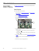
8. Replace the wires from the Converter Snubber Resistors to the Snubber
Boards. See Converter Snubber Resistors - AC Input Only
on page 64 to
identify each resistor.
The black wire goes to J1.
The blue wire goes to J2.
9. Reinstall the bolts at the top of the AC Busbars (R, S, T). Torque to 9.0
N•m (80 lb•in).
10. Reinstall the DC+ and DC- Busbars and torque to 9.0 N•m (80 lb•in).
11. Reassemble remaining components in reverse order.
12. Replace all safety shields and enclosure covers before applying power to the
drive.
IMPORTANT
In the next step, take care to not disturb any of the thermal grease on
the SCR module.
➊➌
➍➋
SCR Torque
First Sequence:
0.7 N-m (6.0 lb.-in.)
SCR Torque
Final Sequence:
5.6 N-m (50 lb.-in.)
➌
➍➋
➊