
User Manual

58 Rockwell Automation Publication 20B-IN025B-EN-P - January 2011
Chapter 3 Component Replacement Procedures
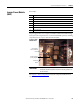
8. Install the Gate Interface Board:
a. Install the Gate Interface Board using the four nuts removed previously.
Torque screws to 2.9 N•m (26 lb•in).
b. Install the supplied Gate Interconnect Harness.
c. Connect wiring between the IGBT and Gate Interface Board as shown
in Gate Interface Board
on page 58.
d. Connect wires to the Current Transducer.
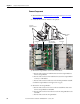
9. Install the three Snubber Capacitors in the reverse order of Remove all
IGBT Snubber components: on page 29.
Torque nuts to 5.6 N•m (50 lb•in).
10. Reassemble remaining components in reverse order.
11. Replace all safety shields and enclosure covers before applying power to the
drive.
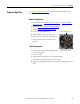
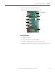
Gate Interface Board
See Chapter 1 - Drive Components to locate the component detailed in these
instructions.
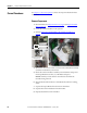
Remove Components
1. Read and follow the Safety Precautions on page 8 and Important Initial
Steps on page 10.
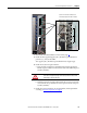
2. Locate the Gate Interface Board to be replaced.
3. Remove the safety cover over the Gate Interface Board.
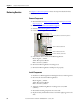
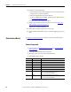
4. Label and disconnect all wires.
Connector Wire Color(s) Connects To:
J1 Red/White/Black J1 on IGBT
J2 Red/White/Black J2 on IGBT
J3 Red/White/Black J3 on IGBT
J4 Orange/Black J23 on Power Interface Board
J5 Blue/White J18 on Power Interface Board
J6 Red/White J4 on IGBT
J7 Red/White/Black J7-W to J7-V (Gate Interface Boards W and V)
J7-V to J7-U (Gate Interface Boards V and U)
J7-U to J8 on Power Interface Board
J8 Black J8-W to J8-V (Gate Interface Boards W and V)
J8-V to J8-U (Gate Interface Boards V and U)
J8-U to J6 on Power Interface Board