
User Manual

Rockwell Automation Publication 20B-IN025B-EN-P - January 2011 55
Component Replacement Procedures Chapter 3
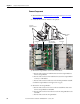
5. Perform Remove all IGBT Snubber components: on page 29.
6. Perform component removal for Gate Interface Board
on page 58.
7. Perform Remove Transitional Busbar on page 28
if Bus Capacitors or the
positive (DC+) Flexible Capacitor Busbars supplied with the kit must be
installed.
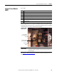
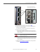
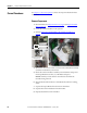
8. Remove the eight screws that secure the IGBT to the chassis. Remove the
IGBT by tipping the right edge out first; return or dispose of it properly.
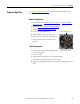
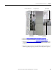
AC Output Busbar Torx
Screws (6)
Output Busbar
Torx Head Bolt
AC Output Busbar
Standoff Nuts (2)
Output Busbar Standoff Nut
and Setscrew
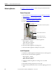
Output Busbar
Hex Head Bolts(2)