
User Manual

46 Rockwell Automation Publication 20B-IN025B-EN-P - January 2011
Chapter 3 Component Replacement Procedures
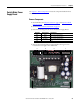
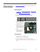
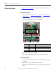
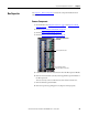
Precharge Board
See Chapter 1 - Drive Components to locate the component detailed in these
instructions.
Remove Components
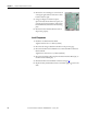
1. Read and follow the Safety Precautions on page 8 and Important Initial
Steps on page 10.
2. Perform Remove Blower Control Panel on page 24
.
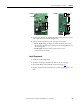
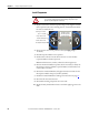
3. For DC input: Label customer wiring to TB2 and then disconnect TB2.
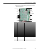
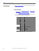
4. Disconnect the all wiring from the Precharge Board.
Note: Label unidentified connectors to simplify reinstallation.
Connector Wire Color(s) Connects To:
AC Input
J1 Red/Black J24 (+BUS IN) on Power Interface Board
J2 Red/White Converter SCR Modules (R, S, T)
J3 Red/White Converter SCR Modules (R, S, T)
DC Input
J1 Red/White Precharge SCR Module
J2 Blue Precharge +DC In Busbar
Red Precharge +DC Out Busbar
Black DC- Bus Capacitor
J3 Red/White J10 on Power Interface Board
TB1 Open
TB2 Blue +DC In Busbar
Red +DC Out Busbar