
User Manual

Rockwell Automation Publication 20B-IN025B-EN-P - January 2011 43
Component Replacement Procedures Chapter 3
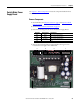
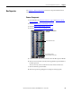
Switch Mode Power
Supply Board
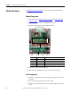
See Chapter 1 - Drive Components to locate the component detailed in these
instructions.
Remove Components
1. Read and follow the Safety Precautions on page 8 and Important Initial
Steps on page 10.
2. Perform Remove Main Control Panel on page 22
.
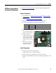
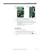
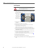
3. Disconnect all wiring from the Switch Mode Power Supply Board.
4. Remove the Switch Mode Power Supply Board mounting torx screw
located at the lower right corner of the board.
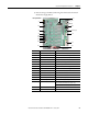
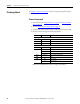
Connector Wire Color(s) Connects To:
J1 Black J2 on Power Interface Board
J2 Black J13 on Power Interface Board
J3 Red/White J12 on Power Interface Board
J4 Open
Screw
Spacers (3)
J2 J4 J3
J1