
User Manual

Rockwell Automation Publication 20B-IN025B-EN-P - January 2011 41
Component Replacement Procedures Chapter 3
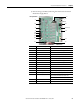
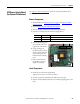
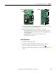
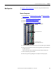
3. Remove wiring to this Board, and wiring from this board to the Switch
Mode Power Supply Board.
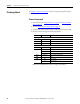
Connector Wire Color(s) Connects To:
J1 Ribbon J2 on Main Control Board (ribbon cable)
J2 Black J1 on Switch Mode Power Supply Board
J6 Black Monitor wire to thermal sensors
J8 Red/White/Black J7-U on U Phase Gate Interface Board
J9 Red/White/Black J1 on 24V Power Supply Board
J10 Red/Black/White/Blue J3 on Precharge Board
J12 Red/White J3 on Switch Mode Power Supply Board
J13 Black J2 on Switch Mode Power Supply Board
J14 Red/White/Black U Phase Current Transducer
J15 Red/White/Black V Phase Current Transducer
J16 Red/White/Black W Phase Current Transducer
J18 Blue/White U, V, W negative (–) gates (lower phase)
J23 Orange/Black U, V, W positive (+) gates (upper phase)
J24 Red/Black J1 on Precharge Board,
TB1 on DC Bus Filter Board (AC input only)
TB1 on DC Bus Filter Board (DC input only)
TB1 Green/Yellow PE on TB11
TB2 Red #33, #34, and #35 on TB11
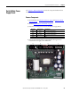
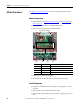
DC input shown
J1
J10
J8
J9
J16
J15
J14
J24
J13
J23
J18
TB2
J6
TB1
J2
Spacers (9)
J12