
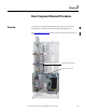
User Manual

26 Rockwell Automation Publication 20B-IN025B-EN-P - January 2011
Chapter 2 Basic Component Removal Procedures
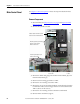
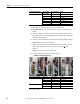
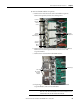
3. Remove the J1 and J2 connectors on the Precharge Board.
4. DC input only: Remove the TB2 connector at the top of the Precharge
Board.
5. Using your fingers or needle-nose pliers, squeeze the tabs of each of the
four spacers and remove the safety shield over the DC Bus Filter Board and
24V Power Supply Board.
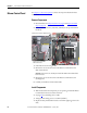
6. Disconnect the red and black wires from TB2 on the DC Bus Filter Board.
Do not disconnect the wires from TB1.
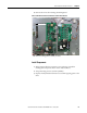
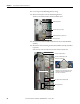
7. Disconnect the black Main Control Panel Thermal Sensor Wire above the
Main Control Board at the connector junction. See page 73
for its
location.
Do not remove the sensor from the bracket.
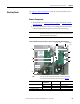
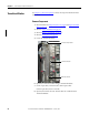
8. Carefully label and disconnect all wiring to TB9.
LT = Left and RT = Right
Power Interface Board J6 J6
J8 J8
J16 U U Phase CT
J15 V V Phase CT
J14 W W Phase CT
J23 UP, VP, WP U, V, W positive gates
J18 UN, VN, WN U, V, W negative gates
Connected Component Wire Color TB9 Terminal Notes
Fan Harness Black 120V, RT side Lower 120V slot
Black N, RT side Upper N slot
Red 120V, LT side Upper 120V slot
White N, LT side Upper N slot
Blower Harness White TB-9, RT side
White TB-10, RT side
Connected Component Label on Wire
or Connector
Label on Board Notes
TB9 Shown with Factory Wiring only