
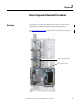
User Manual

Rockwell Automation Publication 20B-IN025B-EN-P - January 2011 25
Basic Component Removal Procedures Chapter 2
Stacking Panel
See Chapter 1 - Drive Components to locate the component detailed in these
instructions.
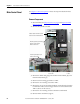
Remove Components
1. Read and follow the Safety Precautions on page 8 and Important Initial
Steps on page 10.
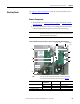
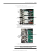
2. All wiring and terminals attached to the Stacking Panel are shown below.
Label any unidentified wiring and terminals before disconnecting.
IMPORTANT
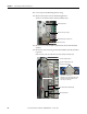
The figure below is shown with the Blower Control Panel removed for
visual clarity. However, you don’t need to remove the Blower Control
Panel to remove the Stacking Panel.
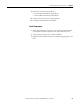
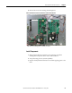
TIP
This step may be performed more easily if you first remove the
Communications Panel following the instructions on page 22
.
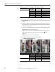
Connected Component Label on Wire
or Connector
Label on Board Notes
Precharge Board J1, J2 J1, J2
TB2 TB2 For DC input only.
DC Bus Filter Board TB2
Thermal Sensor Wire
J8
J18
J23
J6
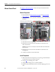
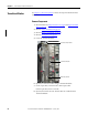
Shown with Main Control Panel, Blower Control Panel and Safety Shield Removed
J14…J16
J1
J2
TB2
TB2
Precharge
Board
(DC input
shown)
DC Bus
Filter Board
Power Interface Board
Thermal Sensor
Wire