
User Manual

18 Rockwell Automation Publication 20B-IN025B-EN-P - January 2011
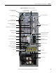
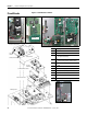
Chapter 1 Component Diagrams and Torque Specs
Torque Specifications
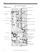
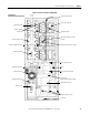
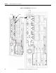
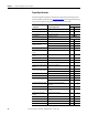
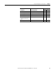
The following table lists fastener locations by component, how the fasteners are
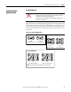
used, and torque specifications. See Torque Sequence
in this chapter for fastening
two-point, four-point, and six-point components to the heat sink.
Torque
Component Fastener Application lb•in N•m
Fan Motor Motor to Fan Cover Assembly 14 2
Fan Cover Assembly Assembly to chassis 26 3
Fan Transformer Transformer to chassis 26 3
Fan Capacitor Capacitor to chassis Hand tighten
MOV Surge Suppressor MOV to chassis 14 2
Converter Snubber Board Board to Input Rectifier 50 6
Balancing Resistor
Resistor to heat sink Initial sequence: 6 0.7
Final sequence: 26 3
Balancing Resistor Wires to Capacitor Busbar Assembly 50 6
Converter Heatsink Thermal
Sensor
Thermistor to heatsink 14 2
Main Control Panel Thermal
Sensor
Thermistor to mounting bracket 14 2
Bus Capacitor Holder Holder to Bus Capacitors 26 3
Capacitor Busbar Assembly Assembly to Bus Capacitors 50 6
Gate Interface Board Board to Power Modules 14 2
Inverter Power Module (IGBT)
Busbar
Busbar to Power Modules 80 9
Inverter Power Module (IGBT)
Module to heat sink Initial sequence: 6 0.7
Final sequence: 32 3.6
DIN Rail (TB1) Rail to chassis 50 6
PE Shortening Bar Bar to TB1 80 9
Converter Power Module (SCR)
SCR to heat sink Initial sequence: 6 0.7
Final sequence: 50 6
Transitional Busbar Assembly Assembly to Power Module Busbar
Assembly
80 9
DC Bus Inductor L1 Inductor to chassis 50 6
Busbar Cable Adaptor Adaptor to Transitional Busbar and DC Bus
Inductor
80 9
Converter Bus and Motor
Busbars
Busbars to all connections 80 9
Wires (PE) Wires to Ground Stud 80 9
Wires Wires to TB1 80 9
Wire (TE) Wire to TB1 50 6
Wires Wires to TB2 7 0.8