
User Manual


Rockwell Automation Publication 20B-IN025B-EN-P - January 2011 17
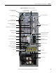
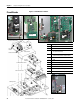
Component Diagrams and Torque Specs Chapter 1
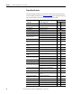
Fastener Torque
Specifications
Torque Sequence
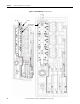
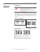
Figure 6 illustrates initial and final tightening sequences for components fastened
to a heat sink using two, four, and six screws. Initial torque is one-third (33.3%) of
final torque, except six-point mountings, which require 0.7 N•m (6 lb•in.) The
numeric illustration labels are for your assistance. Drive components do not carry
these labels.
Figure 6 - Various-Point Mounting
ATTENTION: When mounting components to a drive’s heat sink,
component fastener torque sequences and tolerances are crucial
to component-to-heat sink heat dissipation.
Components can be damaged if initial tightening procedure is not
performed to specification.
Initial
Torque Sequence
Final
Torque Sequence
Two-Point Mounting
Start
End
End Start
1212
Initial
Torque Sequence
Final
Torque Sequence
Four-Point Mounting
End
Start
Start
End
1243
3 421
Note: Do not exceed 0.7 N•m (6 lb•in) on initial torque.
Initial Torque Sequence
Six-Point Mounting
Start
End
Final Torque Sequence
Start
End
62
3 1
4
5
62
3 1
4
5