Installation Instructions PowerFlex 700 Drive - Frame 9 Components Replacement Catalog Numbers XXX XXX XXXX XXX XXX XXX
Important User Information Solid-state equipment has operational characteristics differing from those of electromechanical equipment. Safety Guidelines for the Application, Installation and Maintenance of Solid State Controls (publication SGI-1.1 available from your local Rockwell Automation sales office or online at http://www.rockwellautomation.com/literature/) describes some important differences between solid-state equipment and hard-wired electromechanical devices.
Table of Contents Summary of Changes New and Updated Information. . . . . . . . . . . . . . . . . . . . . . . . . . . . . . . . . . . . . . 5 Preface Introduction. . . . . . . . . . . . . . . . . . . . . . . . . . . . . . . . . . . . . . . . . . . . . . . . . . . . . . . 7 Component Kits . . . . . . . . . . . . . . . . . . . . . . . . . . . . . . . . . . . . . . . . . . . . . . . . . . . 7 Recommended Tools . . . . . . . . . . . . . . . . . . . . . . . . . . . . . . . . . . . . . . . . . . . . . . .
Table of Contents Notes: 4 Rockwell Automation Publication 20B-IN025B-EN-P - January 2011
Summary of Changes This manual contains new and updated information. Changes throughout this revision are marked by change bars, as shown to the right of this paragraph. New and Updated Information This table contains the changes made to this revision.
Summary of Changes Notes: 6 Rockwell Automation Publication 20B-IN025B-EN-P - January 2011
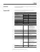
Preface Introduction This publication provides guidelines for replacing the major components in the PowerFlex 700 Frame 9 drive. Component Kits All kits include necessary components, ESD wrist strap and hardware (if required), and thermal grease (if required). Description Printed Circuit Boards Gate Interface Board Precharge Board Kit Catalog No.
Preface Description Miscellaneous (continued) Capacitor Bus Finger Kit Kit Catalog No. Notes SK-G1-FLXBUS1 Included with the kit for Inverter Power Module (IGBT). Can be ordered separately. Includes: • Three positive Flexible Capacitor Busbars • Three negative Flexible Capacitor Busbars For AC input drives only.
Preface Safety Precautions The precautions and general installation requirements provided in the PowerFlex 700 Frame 7-10 Installation Instructions (publication 20B-IN014) and the PowerFlex 700 User Manual (publication 20B-UM002) must be followed with those included here. ATTENTION: To avoid an electric shock hazard, ensure that all power has been removed before proceeding. In addition, before servicing, verify that the voltage on the bus capacitors has discharged.
Preface ATTENTION: This assembly contains parts and sub-assemblies that are sensitive to electrostatic discharge. Static control precautions are required when servicing this assembly. Component damage may result if you ignore electrostatic discharge control procedures. If you are not familiar with static control procedures, refer to Guarding Against Electrostatic Damage, Allen-Bradley publication 8000-4.5.2, or any other applicable ESD protection handbook.
Chapter 1 Component Diagrams and Torque Specs Overview Drive components and their locations are identified in this chapter, as well as torque specifications for fasteners that are part of component removal and replacement.
Chapter 1 Component Diagrams and Torque Specs Figure 1 - Frame 9 - AC Drive Components Drive Shown With Stacking Panel Removed Gate Interface Board (3) Current Transducer (3) Transitional Busbar Flexible Capacitor Busbars (18) Output Busbar (3) DC Bus Capacitor (18) IGBT Interface Board and IGBT (3 each) Tie Down Capacitor Mount (3) Snubber Capacitors (9) for IGBTs Balancing Resistor Converter Snubber Resistors (3) Heatsink Thermal Sensor location Converter Power Module (SCR) (3) Capacitor Bank Fan
Component Diagrams and Torque Specs Chapter 1 Figure 2 - Frame 9 - DC Drive Components Drive Shown With Stacking Panel Removed Gate Interface Board (3) Current Transducer (3) Transitional Busbar Flexible Capacitor Busbars (18) Output Busbar (3) IGBT Interface Board and IGBT (3 each) DC Bus Capacitor (18) Snubber Capacitors (9) for IGBTs Tie Down Capacitor Mount (3) Balancing Resistor Precharge Busbar (Top) Precharge SCR Module Diode Precharge Busbar (Bottom) Capacitor Bank Fan Heatsink Fan (B
Chapter 1 Component Diagrams and Torque Specs Figure 3 - Frame 9 Busbars (AC Drive shown) DC- Bar DC+ Bar Transitional Bus Bar Assembly 14 Rockwell Automation Publication 20B-IN025B-EN-P - January 2011
Component Diagrams and Torque Specs Chapter 1 Figure 4 - Frame 9 (AC input drive shown) DC Link Choke Output Connection (Top) Inverter Snubber Capacitors (3 per IGBT) Gate Interface Board Current Transducer (3) Transitional Busbar DC Capacitor Bank (Under Transitional Busbar) Inverter Power Module IGBT (under Capacitors) Motor Busbars (U, V, W) IGBT Gate and CT Wire Harness Balancing Resistor Stacking Panel Main Control Board (below Communication Panel) Blower Control Panel Communication Panel
Chapter 1 Component Diagrams and Torque Specs Circuit Boards Figure 5 - Circuit Boards on Frame 9 Y _ a Z Y \ X Encoder Board (optional) W [ ` ] Blower Control Panel ^ No.
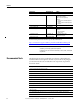
Component Diagrams and Torque Specs Fastener Torque Specifications Chapter 1 Torque Sequence ATTENTION: When mounting components to a drive’s heat sink, component fastener torque sequences and tolerances are crucial to component-to-heat sink heat dissipation. Components can be damaged if initial tightening procedure is not performed to specification. Figure 6 illustrates initial and final tightening sequences for components fastened to a heat sink using two, four, and six screws.
Chapter 1 Component Diagrams and Torque Specs Torque Specifications The following table lists fastener locations by component, how the fasteners are used, and torque specifications. See Torque Sequence in this chapter for fastening two-point, four-point, and six-point components to the heat sink.
Component Diagrams and Torque Specs Chapter 1 Torque Component Fastener Application lb•in N•m Wires Wires to TB3 8 – 10 0.9 – 1.
Chapter 1 Component Diagrams and Torque Specs Notes: 20 Rockwell Automation Publication 20B-IN025B-EN-P - January 2011
Chapter 2 Basic Component Removal Procedures Overview Component removal procedures detailed in this chapter are located on the Stacking Panel and Transitional Busbar assemblies highlighted below. See Circuit Boards on page 16 to identify the various panels that comprise the Stacking Panel assembly.
Chapter 2 Basic Component Removal Procedures Main Control Panel See Chapter 1 - Drive Components to locate the component detailed in these instructions. Remove Components 1. Read and follow the Safety Precautions on page 8 and Important Initial Steps on page 10. 2. Remove safety shields as needed.
Basic Component Removal Procedures Chapter 2 9. Disconnect wire harnesses from TB11 to: • J4 on the Switch Mode Power Supply Board • TB1 and TB2 on the Power Interface Board 10. Label and remove all customer wiring from TB11. 11. Carefully set aside the Main Control Panel. Install Components 1. When instructed for the component you are replacing, reinstall the Main Control Panel Assembly components in the reverse order of removal. 2. Torque panel mounting screws to 2.9 N•m (26 lb•in). 3.
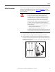
Chapter 2 Basic Component Removal Procedures Blower Control Panel See Chapter 1 - Drive Components to locate the component detailed in these instructions. Remove Components 1. Read and follow the Safety Precautions on page 8 and Important Initial Steps on page 10. 2. Disconnect the three wires (red, white, and blue) at the top of the blower fuse block. Screws (2) to connect to Stacking Panel Red White Blue Screws (2) to connect to Main Control Panel 3. Label and remove all wiring to TB9. 4.
Basic Component Removal Procedures Stacking Panel Chapter 2 See Chapter 1 - Drive Components to locate the component detailed in these instructions. Remove Components 1. Read and follow the Safety Precautions on page 8 and Important Initial Steps on page 10. 2. All wiring and terminals attached to the Stacking Panel are shown below. Label any unidentified wiring and terminals before disconnecting. The figure below is shown with the Blower Control Panel removed for visual clarity.
Chapter 2 Basic Component Removal Procedures Connected Component Power Interface Board Label on Wire or Connector J6 J8 J16 J15 J14 J23 J18 Label on Board Notes J6 J8 U V W UP, VP, WP UN, VN, WN U Phase CT V Phase CT W Phase CT U, V, W positive gates U, V, W negative gates 3. Remove the J1 and J2 connectors on the Precharge Board. 4. DC input only: Remove the TB2 connector at the top of the Precharge Board. 5.
Basic Component Removal Procedures Chapter 2 9. Remove the six nuts for mounting the Stacking Panel. Shown with Main Control Panel and Blower Control Panel Removed Mounting Nuts (6) 10. Remove Stacking Panel; carefully set aside. Install Components 1. When instructed for the component you are replacing, reinstall the Stacking Panel components in the reverse order of removal. 2. Torque mounting screws to 5.6 N•m (50 lb•in). 3.
Chapter 2 Basic Component Removal Procedures Transitional Busbar See Chapter 1 - Drive Components to locate the component detailed in these instructions. Remove Components 1. Read and follow the Safety Precautions on page 8 and Important Initial Steps on page 10. 2. Remove Main Control Panel on page 22. 3. Remove Blower Control Panel on page 24. 4. Remove Stacking Panel on page 25. 5. Locate the Transitional Busbar. DC Choke Output Cables Transitional Busbar Balancing Resistor 6.
Basic Component Removal Procedures Chapter 2 9. Remove all IGBT Snubber components: a. Remove the six nuts that secure each set of Snubber Capacitors. Remove the capacitors, and save nuts and capacitors. Tie Down Capacitor Mount Screw Snubber Capacitor Mount Nuts (6) Snubber Capacitors Tie Down Capacitor Mount Screw b. Remove the two screws that secure each Tie Down Capacitor Mount. Remove the Tie Down Capacitor Mounts and save screws and Capacitor Mounts. c.
Chapter 2 Basic Component Removal Procedures 10. Cut tie wraps for the Balancing Resistor wiring. 11. Disconnect the yellow wire for the Balancing Resistor. You do not need to disconnect the blue and black wires. Balancing Resistor Resistor wiring tie wraps Balancing Resistor yellow wire Disconnect here 12. Remove the four side standoffs and brackets for the Transitional Busbar assembly. 13. Remove the 18 nuts fastening the Transitional Busbar assembly to the Bus Capacitors.
Basic Component Removal Procedures Chapter 2 14. Remove the Transitional Busbar unit.
Chapter 2 Basic Component Removal Procedures Install Components See the photographs in the preceding Transitional Busbar section to identify any components discussed in this section. Positive (DC+) Flexible Capacitor Busbar (short) Negative (DC-) Flexible Capacitor Busbar (tall) IMPORTANT Each IGBT replacement kit includes three positive (DC+) and three negative (DC-) Flexible Capacitor Busbars. The positive ones are shorter (see above) because they attach to the back side of the Transitional Busbar.
Basic Component Removal Procedures Chapter 2 6. Reinstall the screws for the four side standoffs and brackets to secure the Transitional Busbar assembly to the chassis. a. Torque the screws to 5.6 N•m (50 lb•in) to secure the brackets to the four red glastic spacers. b. Torque screws to 2.9 N•m (26 lb•in) to secure the two brackets to the drive chassis. 7. Torque the six setscrews for each IGBT board to 5.6 N•m (50 lb•in).
Chapter 2 Basic Component Removal Procedures Notes: 34 Rockwell Automation Publication 20B-IN025B-EN-P - January 2011
Chapter 3 Component Replacement Procedures Overview Component procedures detailed in this chapter apply to PowerFlex 700 Frame 9 drives for AC or DC input. Removal and replacement instructions for the Stacking Panel and Transitional Bar assemblies are detailed in Chapter 2. Main Control Board See Chapter 1 - Drive Components to locate the component detailed in these instructions. Remove Components 1. Read and follow the Safety Precautions on page 8 and Important Initial Steps on page 10. 2.
Chapter 3 Component Replacement Procedures 6. Holding the Communications Panel, release the cable from the DPI Port 2 clamp and set the Communications Panel aside. Ribbon Cable from Main Control Panel to Power Interface Board Main Control Board Screws (6) Connector Screw TB11 Harness Connector Main Control Board Connector Screw 7. Disconnect the ribbon cable that connects the Main Control Board to the Power Interface Board. 8.
Component Replacement Procedures Chapter 3 Install Components 1. Install the new Main Control Board with six screws and two hex standoffs (if Encoder Board is present). 2. If present, reinstall the Encoder Board with two screws, taking care to match the J7 connectors. 3. Torque screws on Main Control Board and Encoder Board to 0.6 N•m (5 lb•in). 4. Reassemble all components in the reverse order of removal. 5. Reconnect all cables, safety shields and enclosure covers before applying power to the drive.
Chapter 3 Component Replacement Procedures T-Comm Board See Chapter 1 - Drive Components to locate the component detailed in these instructions. Remove Components 1. Read and follow the Safety Precautions on page 8 and Important Initial Steps on page 10. 2. Remove the Main Control Board: a. Remove the HIM board from its slot (if used). b. Disconnect the ribbon cable from the Main Control Board (connects to J1on Power Interface Board). c.
Component Replacement Procedures Chapter 3 b. Remove and save the four mounting screws. 4. If the 20-Comm-C Board is not used, remove the screw securing the TComm grounding tab. T-Comm grounding tab screw T-Comm grounding tab flat T-Comm grounding tab upright 5. Place the tip of a flathead screwdriver between the T-Comm grounding tab and screw mount. Gently pry up until the grounding tab is in an upright position or about 90 degrees from the screw mount. 6.
Chapter 3 Component Replacement Procedures Install Components 1. Install the new T-Comm Board. 2. Verify the board is locked into all seven locking tabs. 3. Carefully bend the T-Comm grounding tab until it is flush with the screw mount on the Main Control Board. 4. Reassemble all components in the reverse order of removal. 5. Reconnect all cables, safety shields and enclosure covers before applying power to the drive.
Component Replacement Procedures Chapter 3 3. Remove wiring to this Board, and wiring from this board to the Switch Mode Power Supply Board.
Chapter 3 Component Replacement Procedures 4. Remove the two mounting torx screws located at the upper right and lower left corners of the board as shown at right. 5. Using your fingers or needle-nose pliers, squeeze the tabs of each of the nine spacers (see previous page for their locations), and separate the Power Interface Board from the mounting plate. 6. Remove the Power Interface Board; return or dispose of it properly. Install Components 1. Install the new Power Interface Board.
Component Replacement Procedures Switch Mode Power Supply Board Chapter 3 See Chapter 1 - Drive Components to locate the component detailed in these instructions. Remove Components 1. Read and follow the Safety Precautions on page 8 and Important Initial Steps on page 10. 2. Perform Remove Main Control Panel on page 22. 3. Disconnect all wiring from the Switch Mode Power Supply Board.
Chapter 3 Component Replacement Procedures 5. Using your fingers or needle-nose pliers, squeeze the tabs of each of the three spacers and separate the Switch Mode Power Supply Board from the mounting plate. 6. Remove the Switch Mode Power Supply Board; return or dispose of it properly. Install Components 1. Install the new Switch Mode Power Supply Board. Tighten board screws to 1.7 N•m (15 lb•in). 2. Reconnect all wiring as detailed in the Table on the previous page. 3.
Component Replacement Procedures 24V Power Supply Board (for Current Transducers) Chapter 3 See Chapter 1 - Drive Components to locate the component detailed in these instructions. Remove Components 1. Read and follow the Safety Precautions on page 8 and Important Initial Steps on page 10. 2. Perform Remove Blower Control Panel on page 24. 3. Remove the safety shield over the 24V Power Supply Board. 4. Disconnect all wiring from the 24V Power Supply Board.
Chapter 3 Component Replacement Procedures Precharge Board See Chapter 1 - Drive Components to locate the component detailed in these instructions. Remove Components 1. Read and follow the Safety Precautions on page 8 and Important Initial Steps on page 10. 2. Perform Remove Blower Control Panel on page 24. 3. For DC input: Label customer wiring to TB2 and then disconnect TB2. 4. Disconnect the all wiring from the Precharge Board.
Component Replacement Procedures DC Input AC Input Chapter 3 TB2 J1 Screw J3 J3 J1 J2 J2 TB1 Spacers (3) Lock Screws (6) 5. For AC input: Remove the Precharge Board mounting torx screw located at the upper left corner of the Precharge Board. 6. Remove the Precharge Board; return or dispose of it properly. • For AC input: Using your fingers or needle-nose pliers, squeeze the tabs of each of the three spacers and separate the Precharge Board from the mounting plate.
Chapter 3 Component Replacement Procedures DC Bus Filter Board See Chapter 1 - Drive Components to locate the component detailed in these instructions. Remove Components 1. Read and follow the Safety Precautions on page 8 and Important Initial Steps on page 10. 2. Remove the safety shield over the DC Bus Filter Board. 3. Disconnect all wiring from TB1 and TB2 terminals.
Component Replacement Procedures Bus Capacitor Chapter 3 See Chapter 1 - Drive Components to locate the component detailed in these instructions. Remove Components 1. Read and follow the Safety Precautions on page 8 and Important Initial Steps on page 10. 2. Perform Remove Main Control Panel on page 22. 3. Perform Remove Stacking Panel on page 25. 4. Perform Remove Transitional Busbar on page 28. Transitional Busbar Unit Removed Bus Capacitor Busbar Bus Capacitor Busbar Nuts and Washers (18 each) 5.
Chapter 3 Component Replacement Procedures Install Components ATTENTION: Install each capacitor so its vent plug is at the top or 12 o’clock. Component and system damage may result if you position any Bus Capacitor incorrectly. 1. Replace setscrews for each new Capacitor using a 3 mm angle hex wrench. Each Capacitor needs a short and long setscrew; see the illustration below for where to install each one.
Component Replacement Procedures Capacitor Bank Fan Chapter 3 See Chapter 1 - Drive Components to locate the component detailed in these instructions. Remove Components 1. Read and follow the Safety Precautions on page 8 and Important Initial Steps on page 10. 2. Perform Remove Main Control Panel on page 22. 3. Perform Remove Stacking Panel on page 25. 4. Locate the Capacitor Bank Fan. Top Fan Mounting Screw 5. Label and disconnect all wires for the fan. 6. Remove the top and bottom mounting screws.
Chapter 3 Component Replacement Procedures Balancing Resistor See Chapter 1 - Drive Components to locate the component detailed in these instructions. Remove Components 1. Read and follow the Safety Precautions on page 8 and Important Initial Steps on page 10. 2. Perform Remove Main Control Panel on page 22. 3. Perform Remove Stacking Panel on page 25. 4. Locate the Balancing Resistor as shown below.
Component Replacement Procedures Inverter Power Module (IGBT) Chapter 3 Kit includes: Qty Component 1 IGBT module with circuit board 1 Gate Interface Board 1 Gate Interconnect Harness 3 Flexible Capacitor Busbar, Positive 3 Flexible Capacitor Busbar, Negative 1 Tie Down Capacitor Mount 3 Snubber Capacitor The photograph below is an example of an IGBT module failure.
Chapter 3 Component Replacement Procedures Remove Components 1. Read and follow the Safety Precautions on page 8 and Important Initial Steps on page 10. 2. Locate the Inverter Power Module to be replaced. Tie Down Capacitor Mount AC Output Busbar Snubber Capacitors IGBT Gate Interface Board Assembly Current Transducer 3. Remove the Output Busbar at the Current Transducer: a. Remove and save the torx head bolt that secures the Output Busbar to the AC Output Busbar. b.
Component Replacement Procedures AC Output Busbar Torx Screws (6) AC Output Busbar Standoff Nuts (2) Output Busbar Torx Head Bolt Chapter 3 Output Busbar Hex Head Bolts(2) Output Busbar Standoff Nut and Setscrew 5. Perform Remove all IGBT Snubber components: on page 29. 6. Perform component removal for Gate Interface Board on page 58. 7. Perform Remove Transitional Busbar on page 28 if Bus Capacitors or the positive (DC+) Flexible Capacitor Busbars supplied with the kit must be installed. 8.
Chapter 3 Component Replacement Procedures Install Components 1. Carefully examine the Transitional Busbar and Bus Capacitors for damage. When replacing any IGBT, it is recommended that you replace all Bus Capacitors. If needed, see Bus Capacitor on page 49 to replace damaged Bus Capacitors. 2. Install the IGBT module. a. Using isopropyl alcohol, thoroughly clean the surface of the Heatsink. b. Verify that the mounting surface of the new IGBT module is clean. If not, clean with isopropyl alcohol. c.
Component Replacement Procedures Chapter 3 1 2 3 4 5 6 Positive (DC+) Flexible Capacitor Busbars Negative (DC-) Flexible Capacitor Busbars Shown with Transitional Busbar and all Flexible Capacitor Busbars installed 4. Reinstall the Transitional Busbar as instructed on page 32. 5. Install the three supplied negative (DC-) Flexible Capacitor Busbars in positions 1, 3, and 5 on the IGBT. The negative (DC-) Flexible Capacitor Busbars have a higher angle. 6. Install the Tie Down Capacitor Mount: a.
Chapter 3 Component Replacement Procedures 8. Install the Gate Interface Board: a. Install the Gate Interface Board using the four nuts removed previously. Torque screws to 2.9 N•m (26 lb•in). b. Install the supplied Gate Interconnect Harness. c. Connect wiring between the IGBT and Gate Interface Board as shown in Gate Interface Board on page 58. d. Connect wires to the Current Transducer. 9. Install the three Snubber Capacitors in the reverse order of Remove all IGBT Snubber components: on page 29.
Component Replacement Procedures Chapter 3 5. Remove the four 7 mm board-mounting nuts. 6. Remove the board; return or dispose of it properly. Gate Interface Board Mounting Nuts (4) J5 J7 J3 J8 J2 J1 J4 J6 Install Components 1. Install the new board. 2. Torque mounting nuts to 1.6 N•m (14 lb•in). 3. Reconnect wiring as detailed in the Table on previous page. 4. Replace all safety shields and enclosure covers before applying power to the drive.
Chapter 3 Component Replacement Procedures Current Transducer See Chapter 1 - Drive Components to locate the component detailed in these instructions. Remove Components 1. Read and follow the Safety Precautions on page 8 and Important Initial Steps on page 10. 2. Locate the Current Transducer to be replaced. 3. Perform Remove the Output Busbar at the Current Transducer: on page 54. Wire to Transducer Transducer Assembly Torx Screws (2) 4.
Component Replacement Procedures Chapter 3 Install Components 1. Mount brackets to the new Current Transducer. Torque screw to 2.9 N•m (26 lb•in). 2. Slide Output Busbar through the Current Transducer assembly with the angled end to the left. 3. Replace the Current Transducer assembly in mounting position by reversing the process used in Step 5. of the removal process. 4. Secure the Current Transducer assembly to the drive chassis with two torx screws. Torque to 2.9 N•m (26 lb•in). 5.
Chapter 3 Component Replacement Procedures Converter Power Module (SCR) - AC Input Only If any Converter SCR module fails, all three SCR modules should be replaced (kit includes all three modules). IMPORTANT See Chapter 1 - Drive Components to locate the component detailed in these instructions. Remove Components 1. Read and follow the Safety Precautions on page 8 and Important Initial Steps on page 10. 2. Perform Remove Main Control Panel on page 22. 3. Perform Remove Stacking Panel on page 25. 4.
Component Replacement Procedures Chapter 3 Install Components 1. Using isopropyl alcohol, thoroughly clean the Heatsink mounting surface where each new SCR module will be installed. 2. Verify that the mounting surface of each new SCR module is clean. If not, clean with isopropyl alcohol. 3. Using a 3- or 4-inch paint roller or putty knife, apply a thin, even coating of the supplied thermal grease to the mounting surface of each new SCR module.
Chapter 3 Component Replacement Procedures Converter Snubber Resistors - AC Input Only See Chapter 1 - Drive Components to locate the component detailed in these instructions. Remove Components Kit includes Snubber Board and Resistor. 1. Read and follow the Safety Precautions on page 8 and Important Initial Steps on page 10. 2. Perform Remove Main Control Panel on page 22. 3. Perform Remove Stacking Panel on page 25. 4. Locate the Snubber Resistor(s) to be replaced.
Component Replacement Procedures Chapter 3 Install Components 1. Using isopropyl alcohol, clean the surface where the new Snubber Resistor will be installed. 2. Verify that the mounting surface of the new Snubber Resistor is clean. If not, clean with isopropyl alcohol. 3. Using a 3-inch paint roller or putty knife, apply a thin even coating of the supplied thermal grease to the mounting surface of the new Snubber Resistor and install. Torque screws to 2.9 N•m (26 lb•in). 4. Reconnect wires. 5.
Chapter 3 Component Replacement Procedures Converter Snubber Board AC Input Only See Chapter 1 - Drive Components to locate the component detailed in these instructions. Remove Components 1. Read and follow the Safety Precautions on page 8 and Important Initial Steps on page 10. 2. Perform Remove Main Control Panel on page 22. 3. Perform Remove Stacking Panel on page 25. 4. Locate the Converter Snubber Board to be replaced.
Component Replacement Procedures Fan Transformer Chapter 3 See Chapter 1 - Drive Components to locate the component detailed in these instructions. Remove Components 1. Read and follow the Safety Precautions on page 8 and Important Initial Steps on page 10. Fan Transformer Label and unplug these two red wires Label and disconnect these three wires Mounting bracket screws (4) 2. Label and unplug or disconnect the five wires for the Fan Transformer. 3.
Chapter 3 Component Replacement Procedures Heatsink Fan - Removal from Back of Drive The Heatsink Fan is located on the back of the drive. (For equipment clearance considerations, the Fan can also be removed from the front of the drive. See Heatsink Fan - Removal from Front of Drive on page 70.) See Chapter 1 - Drive Components to locate the component detailed in these instructions. Remove Components 1. Read and follow the Safety Precautions on page 8 and Important Initial Steps on page 10. 2.
Component Replacement Procedures Chapter 3 Fan Cover Screw Locations on Back of Drive 4 on top and bottom for a total of 8 3 on right side NOTE: No screws on left side Install Components 1. Place Fan assembly into the chassis but not installed in final position. Leave space for accessing Fan cables from the front of the drive. Take care to not pinch wires. Fan Assembly (Front View), Removed from Drive 2. From the front of the drive, reconnect Fan cables.
Chapter 3 Component Replacement Procedures Heatsink Fan - Removal from Front of Drive The Heatsink Fan is located on the back of the drive. These instructions explain how to remove the fan from the front of the drive. Heatsink Fan (DC input drive shown) See Chapter 1 - Drive Components to locate the component detailed in these instructions. Remove Components 1. Read and follow the Safety Precautions on page 8 and Important Initial Steps on page 10. 2.
Component Replacement Procedures Chapter 3 Do not disconnect the U, V, or W Busbars at the bottom. AC Drive Shown 17 mm bolt on DC+ Busbar 17 mm bolt on DC– Busbar Do not disconnect Busbars at the bottom. 16 mm bolts 6. AC input only: Disconnect all busbars where they connect to the Converter SCR modules with 16 mm bolts. Disconnect wiring. Do not disconnect the U, V, or W Busbars at the bottom. 7.
Chapter 3 Component Replacement Procedures Do not disconnect the U, V, or W Busbars at the bottom. 11 mm Nut and Setscrew 17 mm Bolts (2) Current Transducer U, V, and W Busbars Output Busbar 8. Remove the four 10 mm nuts for the busbars mounting plate.
Component Replacement Procedures Chapter 3 9. Remove the entire busbar and mounting plate assembly. Set aside. AC Input Drive DC Input Drive 10. Unplug the fan cables. 11. For AC input only: Remove the MOV Surge Suppressor as instructed on page 79. 12. Remove the left busbar mounting plate bracket.
Chapter 3 Component Replacement Procedures 13. Remove the 12 exterior screws on the fan mounting plate. Fan Mounting Plate Screws (12) Busbar Mounting Plate Bracket 14. Carefully remove the mounting plate and fan through the front of the drive chassis; you may need to pry the mounting plate away from the gasket. The fan housing remains mounted on the chassis. Install Components 1. Remove the new fan housing from the new fan and mounting plate. Discard the new fan housing. 2.
Component Replacement Procedures Thermal Sensors Chapter 3 In the AC input drive, the Thermal Sensor system consists of: • A connector to J8 on each of the three Gate Interface Boards. • A sensor secured to the Heatsink above the SCR modules. • A sensor secured to the upper mounting bracket for the Main Control Panel. • A connector to J6 on the Power Interface Board. • Wiring to TB9 (terminals 9 and 10) on the Stacking Panel.
Chapter 3 Component Replacement Procedures Thermal Sensor wiring for DC input drive TO CNV TO INV TO INV CNV BOT Main Control Panel Thermal Sensor CNV TOP Main Control Panel Thermal Sensor J6 TB9 - 9 & 10 CNV-2 TO INV TB9 - 9 & 10 CNV-3 Power Interface Board J6 Power Interface Board 9 10 CNV-1 TO INV TB9 - 9 & 10 TB15 OUT TB15 OUT (jumpered) DC Choke Plate Heatsink Thermal Sensor TO INV TO CNV Heatsink Thermal Sensor B TO INV B TO INV A A J8-U J8-U J8-V J8-V J8-W J8-W Ther
Component Replacement Procedures Chapter 3 Remove Components 1. Read and follow the Safety Precautions on page 8 and Important Initial Steps on page 10. 2. Cut the wire ties for the wiring harness along the Gate Interface Boards. Heatsink Thermal Sensor & Screw 3. Note wire routing and location of sensors. MCP Thermal Sensor Wiring Harness End 4. For the Main Control Panel thermal sensor, remove its screw and nut on the Main Control Panel and disconnect the other end from the wiring harness.
Chapter 3 Component Replacement Procedures DC Link Choke AC Input Only See Chapter 1 - Drive Components to locate the component detailed in these instructions. Remove Components 1. Read and follow the Safety Precautions on page 8 and Important Initial Steps on page 10. 2. Locate the DC Link Choke. L1 L4 L2 TB15 L3 DC Choke Plate Mounting Screws (4) 3. Label and disconnect DC Choke connectors (L1…L4). 4. Label and disconnect wiring to TB15. 5.
Component Replacement Procedures MOV Surge Suppressor AC Input Only Chapter 3 See Chapter 1 - Drive Components to locate the component detailed in these instructions. Remove Components 1. Read and follow the Safety Precautions on page 8 and Important Initial Steps on page 10. 2. Perform Remove Main Control Panel on page 22. 3. Perform Remove Stacking Panel on page 25. 4. Locate the MOV Surge Suppressor assembly. MOV 5. Note wire placement and connections.
Chapter 3 Component Replacement Procedures Precharge SCR Module and Diode - DC Input Only See Chapter 1 - Drive Components to locate the component detailed in these instructions. Remove Components 1. Read and follow the Safety Precautions on page 8 and Important Initial Steps on page 10. 2. Perform Remove Main Control Panel on page 22. 3. Perform Remove Stacking Panel on page 25. 4. Locate the Precharge SCR module and Diode to be replaced. Busbars SCR Diode 5.
Component Replacement Procedures Chapter 3 3. Using a 3- or 4-inch paint roller or putty knife, apply a thin, even coating of the supplied thermal grease to the mounting surface of each SCR module and Diode. WARNING: In the next step, be sure to properly install the modules as shown. If you install the SCR incorrectly, it will not work. If you install the Diode incorrectly, then the Drive and the Bus Capacitors may not operate properly and may prematurely fail.
Chapter 3 Component Replacement Procedures Notes: 82 Rockwell Automation Publication 20B-IN025B-EN-P - January 2011
Rockwell Automation Support Rockwell Automation provides technical information on the Web to assist you in using its products. At http://www.rockwellautomation.com/support/, you can find technical manuals, a knowledge base of FAQs, technical and application notes, sample code and links to software service packs, and a MySupport feature that you can customize to make the best use of these tools.