
User Manual


14 Publication 20B-IN22B-EN-P — December 2009
Chapter 2 Component Replacement Procedures
Power Interface Board
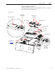
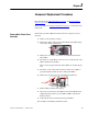
Remove Components
1. Perform Remove Main Control Panel Assembly on page 13.
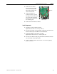
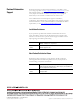
2. Remove all remaining wiring and cabling from the Power Interface
Board as indicated in the table below.
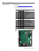
Connector
Frame
Connected Components
78910
J1 XXXXMain Control Board
J10 X X X Precharge Board (only on DC input systems)
J8 X X X U Phase Gate Interface Board
J9 X X 24V Power Supply Board
J16 XXXXW Phase CT
J15 XXXXV Phase CT
J14 XXXXU Phase CT
J24 X X X X +Bus IN of Power Interface Board
to J1 of Precharge Board
J13 X X X X Switch Mode Power Supply Board
J12 X X X X Switch Mode Power Supply Board
J23 X X X X U, V, W positive gates (upper phase)
J18 X X X X U, V, W negative gates (lower phase)
TB2 XXXXTB11
J7 X Monitor Wire to thermal sensors
J6 X X X Monitor Wire to thermal sensors
TB1 XXXXTB11
J2 X X X Switch Mode Power Supply Board
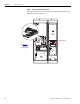
Frame 9
DC input
shown
J1
J10
J8
J9
J16
J15
J14
J24
J13 J12
J23
J18
TB2
J6
TB1
J2
J7