
User Manual


Publication 20B-IN22B-EN-P — December 2009 13
Chapter
2
Component Replacement Procedures
Read and follow the Safety Precautions on page 6 and Important Initial
Steps on page 8 for all these instructions.
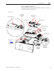
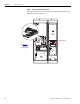
Refer to the figures in Component Diagrams on page 9
as needed for these
instructions.
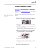
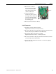
Remove Main Control Panel
Assembly
Perform this procedure only when instructed for the component you are
replacing.
1. Remove safety shields as needed.
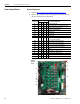
2. Remove the ribbon cable going from the Main Control Board (J2)
to the Power Interface Board (J1).
3. Remove the two screws and washers on the Main Control Panel
below TB11.
4. For Frames 9 and 10: Remove the two screws on the left side of the
Main Control Panel assembly.
These screws are larger than those below TB11. Do not mix the two
sets.
5. For Frame 7 only: Verify that all wiring to lower side of TB11 is
properly labeled and then disconnect wiring from TB11.
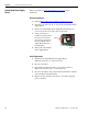
6. Remove the two nuts at the top of the Main Control Panel.
7. Remove Main Control Panel; support.
8. Disconnect wire harnesses from TB11 to the Switch Mode Power
Supply Board (J4 connector) and at TB1 and TB2 on the Power
Interface Board.
9. Label and disconnect all customer wiring from TB11.
10. Carefully set the Main Control Panel aside.
CAUTION
HOT SURFACES
!
Nuts