PowerFlex® 700 Drive Power Interface Board and Switch Mode Power Supply Board Replacement - Frames 7, 8, 9, 10 Installation Instructions
Important User Information Solid state equipment has operational characteristics differing from those of electromechanical equipment. Safety Guidelines for the Application, Installation and Maintenance of Solid State Controls (publication SGI-1.1 available from your local Rockwell Automation sales office or online at http://literature.rockwellautomation.com) describes some important differences between solid state equipment and hard-wired electromechanical devices.
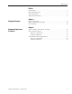
Table of Contents Preface Introduction . . . . . . . . . . . . . . . . . . . . . . . . . . . . . . . . . . . . . . . . . . . . . . . Recommended Tools. . . . . . . . . . . . . . . . . . . . . . . . . . . . . . . . . . . . . . . . Safety Precautions . . . . . . . . . . . . . . . . . . . . . . . . . . . . . . . . . . . . . . . . . . Important Initial Steps. . . . . . . . . . . . . . . . . . . . . . . . . . . . . . . . . . . . . . . 5 5 6 8 Chapter 1 Component Diagrams Drive Components . . . . . . . . . .
Table of Contents Notes: 4 Publication 20B-IN22B-EN-P — December 2009
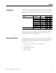
Preface Introduction This publication provides guidelines for replacing/installing Power Interface Boards and Switch Mode Power Supply Boards in the PowerFlex 700 drive for Frames 7, 8, 9, and 10. All kits include the board, wrist strap and hardware (if required). Description Power Interface Board Kit Catalog No.
Preface Safety Precautions The precautions and general installation requirements provided in the PowerFlex 700 Frame 7-10 Installation Instructions (publication 20B-IN014) and the PowerFlex 700 User Manual (publication 20B-UM002) must be followed in addition to those included here. To avoid an electric shock hazard, ensure that all power has been removed before proceeding. In addition, before servicing, verify that the voltage on the bus capacitors has discharged.
Preface ATTENTION ATTENTION ATTENTION ATTENTION ATTENTION Publication 20B-IN22B-EN-P — December 2009 This assembly contains parts and sub-assemblies that are sensitive to electrostatic discharge. Static control precautions are required when servicing this assembly. Component damage may result if you ignore electrostatic discharge control procedures. If you are not familiar with static control procedures, reference Allen-Bradley Publication 8000-4.5.
Preface Important Initial Steps Read and follow these statements before performing any service on the drive. • • • • • • 8 Read and follow the precautions in Safety Precautions on page 6. Identify components to be replaced using the figures in Component Diagrams on page 9. Remove protective shields only as necessary. Before disconnecting any wire or cable, verify that it is labeled. Also, when removing components, note hardware type and location.
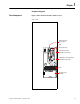
Chapter 1 Component Diagrams Drive Components Figure 1 Main Control Panel Assembly - Relative Location Frame 7 shown Main Control Panel Thermal Sensor HIM Main Control Panel Power Interface Board (under Main Control Panel) ! CAUTION HOT SURFACES Switch Mode Power Supply Board (under Main Control Panel) TB11 25 AMPERES RMS MAXIMUM PE ALLEN-BRADLEY MADE IN U.S.A.
Chapter 1 Component Diagrams Main Control Panel Assembly Figure 2 Main Control Panel Assembly (Frame 7 AC input drive shown) Bottom of Drive Top of Drive Communication (Comm) Module Mounting Board and HIM Communication Panel TB11 and Main Control Board Main Control Panel Switch Mode Power Supply Board and Power Interface Board Stacking Panel Front Back Components are listed left to right for each level Note: Components are shown as seen from right side without drive covers.
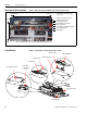
Component Diagrams Chapter 1 Figure 4 Circuit Boards - Frames 8…10 This diagram indicates the location of all boards on Frames 8…10 except for the Precharge Board on Frame 10. Frame 8 shown Power Interface Board Switch Mode Power Supply Board T-Comm Interface Options may be installed here HIM Cradle/Board HIM Support Plate Encoder Board Control Board Main Control Panel Precharge Board See Figure 5 for Frame 10 Precharge Board.
Chapter 1 Component Diagrams Figure 5 Frame 10 AC Input Circuit Boards This diagram indicates the location of the Precharge Board on Frame 10 as different from that on Frames 7…9. DANGER DC+ DANGER DANGER ! DANGER RISK OF SHOCK REPLACE AFTER SERVICING TB9 8 AMPERES RMS MAXIMUM 120 IN1 120 IN2 3 4 5 6 ! Precharge Board DANGER RISK OF SHOCK REPLACE AFTER SERVICING TB11 25 AMPERES RMS MAXIMUM PE ! See Figure 4 for location of boards other than Precharge Board.
Chapter 2 Component Replacement Procedures Read and follow the Safety Precautions on page 6 and Important Initial Steps on page 8 for all these instructions. Refer to the figures in Component Diagrams on page 9 as needed for these instructions. Remove Main Control Panel Assembly Perform this procedure only when instructed for the component you are replacing. 1. Remove safety shields as needed. 2. Remove the ribbon cable going from the Main Control Board (J2) to the Power Interface Board (J1). 3.
Chapter 2 Component Replacement Procedures Power Interface Board Remove Components 1. Perform Remove Main Control Panel Assembly on page 13. 2. Remove all remaining wiring and cabling from the Power Interface Board as indicated in the table below.
Component Replacement Procedures 3. Remove the two Power Interface Board mounting star screws located at the upper right and lower left corners of the board. 4. Using your fingers or needle-nose pliers, squeeze the wings of each of the nine (9) spacers and separate the Power Interface Board from the mounting plate. Chapter 2 Screws Frame 7 shown 5. Remove the Power Interface Board. Install Components 1. Install the new Power Interface Board. Tighten board screws to 1.7 N-m (15 lb.-in.) 2.
Chapter 2 Component Replacement Procedures Switch Mode Power Supply Board Refer to the figures in Component Diagrams on page 9 for these instructions. Remove Components 1. Perform Remove Main Control Panel Assembly on page 13. 2. Disconnect all cables (J2, J4, J3, J1) from the Switch Mode Power Supply Board. 3. Remove the Switch Mode Power Supply Board mounting star screw located at the lower right corner of the board. 4.
Component Replacement Procedures Chapter 2 Notes: Publication 20B-IN22B-EN-P — December 2009 17
Chapter 2 Component Replacement Procedures Notes: 18 Publication 20B-IN22B-EN-P — December 2009
Rockwell Automation Support Rockwell Automation provides technical information on the Web to assist you in using its products. At http://support.rockwellautomation.com, you can find technical manuals, a knowledge base of FAQs, technical and application notes, sample code and links to software service packs, and a MySupport feature that you can customize to make the best use of these tools.