
Instruction Manual

PDC24
/
PAC
October
200
5
–
Issue 3
9
Tri
guard
SC300E PDC24 / PAC Chassis Power Supplies
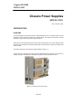
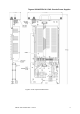
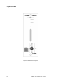
SWITCHES AND INDICATORS
All
user
interface
is
via
the
front
panel
(Figure
2
-
3
).
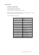
The
following
facilities
are
provided:
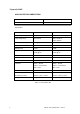
Table
2
-
3.
Front
panel
facilities
LED
Indicator
Indication
Normal
LED
(green)
Illuminates
to
indicate
normal
operation
Power
Share
LED
(yellow)
Illuminates
to
indicate
that
power
sharing
is
in
balance.
It
can
extinguish
if
the
other
PSU
supplies
about
1.3A
more
current.
Balance
can
be
adjusted
(see
Section
3.3
Field
functionality
tests).
NOTE:
If
one
PSU
is
removed,
the
Power
share
LED
on
the
remaining
PSU
illuminates.
Fault
LED
(red)
Illuminates
to
indicate
an
over
temperature
or
undervoltage
fault
condition
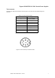
TEST
8
-
way
270º
DIN
socket.
Use
as
described
in
XRefColorection
functionality
tests,
Default
¶ Font.
A mating
connector
is
available
free
of
charge.
ON/OFF
3A
(PAC)/10A
(PDC24)
circuit
breaker
and
ON/OFF
push
switch
for
supply
voltage.
O/P
Adi
Screwdriver
adjustment
of
current
sharing/output
voltage.