
Instruction Manual
8
PDC24
/
PAC
October
200
5
–
Iss
ue 3
Triguard
SC300E
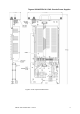
THEORY OF OPERATION
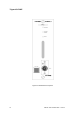
Main power flow
The
5.4V
output
allows
for
a drop
of
about
0.4V
across
the
auctioneering
diodes
in
each
module
supplied.
The
output
voltage
is
fed
back
to
the
SMPS
control
circuits
via
the
+ve
and
-
ve
sense
lines.
The
SMPS
then
compensates
for
any
voltage
drop
along
the
power
supply
lines
by
increasing
its
output
voltage.
The
rated
output
voltage
is
thus
present
at
the
load
rather
than
at
the
PSU
output
terminals.
The
-
ve
sense
input
to
the
SMPS
is
modified
by
the
power
share
system.
The
5V
supply
current
sensor
is
a 0.005
-
ohm
resistance
formed
by
two
resistors
in
parallel.
The
voltage
developed
across
the
resistors
is
used
as
a measure
of
output
current
by
the
power
share
and
fa
ult
alarm
circuits.
Various
system
voltages
are
connected
by
current
limiting
resistors
to
individual
pins
of
the
test
socket
on
the
front
panel.
The
‘current
limiters’
protect
the
system
against
accidental
short
circuits
on
any
of
the
test
socket
pins.
W
ARNING
Plant
shutdown
-
Adjusting
the
power
supplies
in
a running
system
could
result
in
a
plant
shutdown.
Power share system
The
power
share
control
circuit
accepts
inputs
from
the
5V
supply
current
sensor,
the
+ve
and
-
ve
sense
lines,
the
output
adjustment
trimmer
(O/P
ADJ)
on
the
front
panel,
and
the
power
share
line.
It
drives
the
power
share
line,
the
power
share
LED
on
the
front
panel,
and
the
voltage
on
the
-
ve
sense
line
input
to
the
SMPS.
Normally
the
voltage
at
the
-
ve
sense
input
to
the
SMPS
is
close
to
that
on
the
-
ve
sense
line
from
the
backplane.
When
the
power
share
control
circuit
detects
that
an
increase
in
output
current
is
required
to
maintain
power
balance,
the
-
ve
sense
SMPS
voltage
drops,
so
that
the
voltage
between
the
+ve
and
-
ve
se
nse
lines
is
now
greater.
The
SMPS
then
increases
its
output
voltage.
Fault alarm system
The
power
fail
output
from
the
SMPS
switches
from
logic
high
to
low
just
before
the
SMPS
output
fails
(i.e.
to
give
advance
warning
following
a failure
of
the
ac/dc
input
supply).
The
fault
alarm
circuits
de
-
energise
the
fault
relay
in
response
to:
• The
power
fail
signal
• An
input
from
a 70ºC
thermal
cut
-
out
on
the
SMPS
• An
undervoltage
output
condition
detected
on
the
+ve
and
-
ve
sense
lines
A set
of
changeover
cont
acts
controls
the
Fault
and
Normal
LEDs
on
the
front
panel.
Another
pair
of
relay
contacts
is
available
to
operate
an
external
alarm.
These
contacts
open
under
fault
conditions.