
Instruction Manual
4
PDC24
/
PAC
October
200
5
–
Iss
ue 3
Triguard
SC300E
TECHNICAL
DESCRIPTIO
N
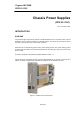
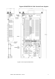
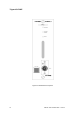
PHYSICAL
The
PSU
comprises
a front
plate
mounted
at
right
angles
to
a chassis
plate.
All
the
user
controls
and
indicators
are
mounted
on
the
front
plate
as
shown
in
Figure
1
-
1.
The
chassis
plate
supports
three
main
items:
• Power
supply
unit:
A self
-
contained
switch
-
mode
power
supply
unit
(SMPS).
•
Front
panel
PCB:
Contains
printed
wiring
and
physical
support
for
the
controls
and
indicators
that
are
viewed
and
accessed
from
the
front
panel.
• PSU
interface
PCB:
Contains
the
power
share
and
fault
alarm
circuits.
Interfaces
these
circuits
and
the
SMPS
to
the
SC300E
chassis
backplane
via
connector
PL3.
A ribbon
cable
connects
the
front
panel
PCB
to
the
SMPS.
A mechanical
stop
fitted
to
the
AC
system
chassis
power
supply
slots
(marked
AC
STUD)
prevents
the
insertion
of
a PDC24
into
a PAC
slot.