
Instruction Manual
PDC24
/
PAC
October
200
5
–
Issue 3
11
Tri
guard
SC300E PDC24 / PAC Chassis Power Supplies
SERVICING
SCOPE
The
PSUs
have
no
field
replaceable
parts.
Faulty
units
should
be
returned
for
repair.
CONFIGURATION
No
configurable
links.
FIELD FUNCTIONALITY TESTS
The
12V
supply
is
not
calibrated.
Set
up
the
5V
supply
as
follows.
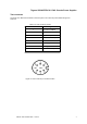
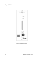
For
each
test
use
a digital
voltmeter
across
the
relevant
pair
of
pins
on
the
8
-
way
DIN
socke
t.
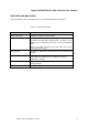
Output
voltage
(5V)
Measure
across
pins
6 and
7.
The
voltage
should
be
5.4V
±0.01V.
Output
voltage
(12V)
Measure
across
pins
1 and
2.
The
voltage
should
be
within
the
range
11.5V
to
12.5V.
Output
current
(5V)
Measure
the
voltage
between
pins
1 and
4.
This
should
be
proportional
to
the
current
supplied
by
the
PSU
at
0.005
Volts
per
Amp.
The
current
supplied
will
depend
on
the
configuration
of
modules
within
the
system.
SMPS
Output
voltage
(5V)
Measure
the
voltage
between
pins
3 and
6.
This
should
not
exceed
5.8V.
A higher
value
(nominally
6.3V)
may
initiate
an
overvoltage
trip.
Power
share
line
Measure
the
voltage
between
pins
1 and
5.
The
voltage
will
depend
on
the
currents
being
provided
by
both
power
supplies.
It
should
not
exceed
4.0V
at
maximum
current.
Power
fail
interrupt
This
can
be
monitored
on
pin
8.
It
is
a logic
output
that
is
normally
pulled
up
resistively
to
+5V,
but
is
pulled
low
if
the
ac/dc
input
supply
fails.