MV SMC-Flex OEM Components Bulletin 1503E Installation Instructions
Important User Information Read this document and the documents listed in the Additional Resources section about installation, configuration, and operation of this equipment before you install, configure, operate, or maintain this product. Users are required to familiarize themselves with installation and wiring instructions in addition to requirements of all applicable codes, laws, and standards.
Table of Contents Chapter 1 Introduction Scope ....................................................................................... 1-1 Additional Publications .......................................................... 1-2 Chapter 2 Receiving and General Information Receiving ............................................................................... 2-1 Handling Procedures for Electrostatic Sensitive Devices ....... 2-1 Standards and Codes ......................................................
ii Table of Contents Chapter 6 Contactor Installation Introduction .............................................................................. 6-1 Main and Bypass Contactors ................................................... 6-1 Bypass Contactor .................................................................... 6-1 Main and Bypass Contactor Wiring Configuration ................ 6-2 Bypass Contactor Control Panel ............................................. 6-3 IntelliVAC Control Module ..........
Chapter 1 Introduction Scope This document pertains to the Bulletin 1503E MV SMC Flex OEM components. Most of the components described herein are provided in various 1503E kits; however, some of the devices described are not provided. These must be acquired separately. The power stack frame is a complete three-phase power system used in solid-state reduced voltage motor controllers (refer to Figure 3.1). Power stacks are also available as a set of loose three-phase components (refer to Figure 4.1).
1-2 Introduction 1503E-IN001E-EN-P – June 2013
Chapter 2 Receiving and General Information Receiving Handling Procedures for Electrostatic Sensitive Devices Refer to Getting Started, General Handling Procedures for Medium Voltage Controllers - Publication MVB-5.0. This document is included with your shipment and contains information regarding receiving, unpacking, initial inspection, handling, storage, and site preparation.
2-2 Receiving and General Information Standards and Codes 1503E-IN001E-EN-P – June 2013 Important: It is recommended that the user be familiar with the following safety and design standards and codes, and any additional local codes that a medium voltage controller must comply with: • CEC (Canadian Electrical Code) • CSA 22.2 No.
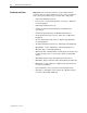
Chapter 3 Power Stack Frame Installation Identification A power stack frame is shown below in Figure 3.1 (3300/4160 V frame shown). Figure 3.1 – MV SMC Flex OEM Power Stack Frame Verify the voltage and current rating of the OEM frame using the information located on the nameplate at the front of the frame (see Figure 3.2). Refer to Table 3.A for the frame description and catalog numbers. Figure 3.
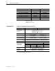
3-2 Power Stack Frame Installation Specifications Description of Frame Options Catalog Number Part Number 1000V, 180 A, 3 phase, 50/60 Hz 1000V, 360 A, 3 phase, 50/60 Hz 2300V, 180 A, 3 phase, 50/60 Hz 2300V, 360 A, 3 phase, 50/60 Hz 3300V, 180 A, 3 phase, 50/60 Hz 3300V, 360 A, 3 phase, 50/60 Hz 4160V, 180 A, 3 phase, 50/60 Hz 4160V, 360 A, 3 phase, 50/60 Hz 1503E-FRZ1T 1503E-FRZ1A 1503E-FRAT 1503E-FRAA 1503E-FRCT 1503E-FRCA 1503E-FRET 1503E-FREA 80187-547-51 80187-547-52 80187-547-53 80187-54
Power Stack Frame Installation Sizing the Enclosure ATTENTION 3-3 The enclosure for the power stack frame assembly must be adequately sized to provide sufficient airflow to cool the units. Failure to provide adequate cooling may result in reduced duty cycles or component failure. Use the information included in Table 3.B to assist in determining the enclosure size. Dimensions The power stack frame dimensions are shown in Figure 3.3 below. The dimensions are the same for all frame catalog numbers.
3-4 Power Stack Frame Installation Frame Layout Refer to Figure 3.4 for the main components of the OEM SMC frame. Voltage Sensing Board located on underside of mounting panel Lifting Clip Heatsink Assembly Current Loop Gate Driver Board Current Loop Gate Driver Power Assembly Power Phase A Power Phase B Power Phase C Front View Figure 3.
Power Stack Frame Installation Anchoring 3-5 Mounting holes are provided in the frame and are suitable for 0.5 in. (M12) diameter anchor bolts (refer to Figure 3.5). The frame is designed to be anchored in the upright position and on a level surface. Do not attempt to mount the frame upside down or at any angle that is not level. Improper anchoring may cause injury to personnel and/or damage to the equipment. ATTENTION 640 [25.2] 521 [20.5] 778 [30.6] 900 [35.
3-6 Power Stack Frame Installation Power Connections ATTENTION I MPORTANT To avoid shock hazard, lock out incoming power to power cables when completing connections. Failure to do so may result in severe burns, injury or death. It is the responsibility of the OEM to ensure that suitable line and load cables are used to satisfy the requirements of the equipment and meet local electrical codes.
Power Stack Frame Installation Grounding Current Loop Gate Drive Power Assembly (CLGD) ATTENTION 3-7 It is the responsibility of the OEM to ensure that the final enclosure is suitably bonded to ground, and that provisions for grounding are made according to local electrical codes and standards. The CLGD power assembly is mounted on the front bottom of the frame (refer to Figure 3.4). All secondary connections are pre-wired for the power stack frame.
3-8 Power Stack Frame Installation 1503E-IN001E-EN-P – June 2013
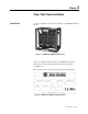
Chapter 4 Power Stack Installation Identification A power stack (single phase, 3300/4160V) power stack is shown below in Figure 4.1. Figure 4.1 – Single-phase Power Stack Verify the voltage and current rating of the OEM power stacks by examining the label and referencing it to the information in Table 4.A. Table 4.
4-2 Power Stack Installation Identification (cont.) In addition to the power stacks, a voltage sensing board is to be connected in the power circuit. Table 4.B lists the voltage sensing board part number, which is used for all power stacks. Table 4.
Power Stack Installation Specifications Table 4.
4-4 Power Stack Installation Torque Requirements All electrical connections must be torqued to the specifications shown in Table 4.D. ATTENTION Ensure that all electrical connections are torqued to the correct specification. Failure to do so may result in damage to the equipment and/or injury to personnel. Table 4.D – Torque Requirements Hardware Power Stack Mounting Recommended Torque 1/4 in. 6 ft·lb (8 N·m) 5/16 in. 11 ft·lb (15 N·m) 3/8 in. 20 ft·lb (27 N·m) 1/2 in.
Power Stack Installation 4-5 OVERALL DIMENSIONS: WIDTH: 186.4 [7.34] HEIGHT: 426.7 [16.80] DEPTH: 457.7 [18.02] WEIGHT: 35 kg [77 lbs.] Mounting Holes for M10 (3/8”) hardware (4 places) Dimensions in millimeters [inches] 186.4 [7.34] 426.7 [16.80] Front View 446.9 [17.60] 457.7 [18.02] Side View 457.7 [18.02] 214.4 [8.44] Note: All dimensions include mounting bracket. 12.7 [0.50] 139.7 [5.50] Bottom View Figure 4.
4-6 Power Stack Installation OVERALL DIMENSIONS: WIDTH: 501.2 [14.73] HEIGHT: 444.1 [17.49] DEPTH: 461.5 [18.17] WEIGHT: 44 kg [97 lbs] Dimensions in millimeters [inches] 501.2 [19.73] 309.8 [12.20] 88.9 [3.50] 461.4 [18.17] 98.6 [3.88] 125.3 [4.93] 444.1 [17.49] 50.8 [2.00] 414.2 [16.31] 102.6 [4.04] 50.8 [2.00] 203.3 [8.01] Mounting Holes for M10 (3/8”) hardware (4 places) Front View Figure 4.
Power Stack Installation 4-7 OVERALL DIMENSIONS: WIDTH: 186.7 [7.35] HEIGHT: 582.2 [22.92] DEPTH: 454.4 [17.89] WEIGHT: 38 kg [83 lbs] Dimensions in millimeters [inches] Mounting Holes for M10 (3/8”) hardware (4 places) 186.7 [7.35] 582.2 [22.92] Front View 443.5 [17.46] 454.4 [17.89] Side View 454.4 [17.89] Note: All dimensions include mounting bracket. 214.4 [8.44] 12.7 [0.50] 139.7 [5.50] Bottom View Figure 4.
4-8 Power Stack Installation Power Stack Mounting (cont.) OVERALL DIMENSIONS: WIDTH: 394.7 [15.54] HEIGHT: 611.2 [24.06] DEPTH: 461.4 [18.17] WEIGHT: 51 kg [113 lbs.] Dimensions in millimeters [inches] 394.7 [15.54] 203.3 [8.01] 88.9 [3.50] 461.4 [18.17] 98.6 [3.88] 189.8 [7.47] 581.3 [22.88] 50.8 [2.00] 611.2 [24.06] 205.2 [8.08] 50.8 [2.00] Front View Mounting holes for M10 (3/8”) hardware (4 places) Side View Figure 4.
Power Stack Installation 4-9 OVERALL DIMENSIONS: WIDTH: 451.9 [17.79] HEIGHT: 617.0 [24.29] DEPTH: 399.3 [15.72] WEIGHT: 42 kg [93 lbs] Dimensions in millimeters [inches] 451.9 [17.79] 88.9 [3.50] 260.5 [10.26] 399.3 [15.72] 101.8 [4.01] 212.6 [8.37] 617.0 [24.29] 50.8 [2.00] 587.1 23.11] 193.5 [7.62] 50.8 [2.00] Front View Mounting holes for M10 (3/8”) hardware (4 places) Side View Figure 4.
4-10 Power Stack Installation Power Stack Mounting (cont.) OVERALL DIMENSIONS: WIDTH: 394.6 [15.54] HEIGHT: 625.9 [24.64] DEPTH: 461.4 [18.17] WEIGHT: 57 kg [125 lbs] Dimensions in millimeters [inches] 394.6 [15.54] 203.2 [8.00] 88.9 [3.50] 461.4 [18.17] 98.6 [3.88] 235.3 [9.26] 50.8 [2.00] 595.9 [23.46] 193.5 [7.52] 625.9 [24.64] 50.8 [2.00] Mounting holes for M10 (3/8”) hardware (4 places) Front View Figure 4.
Power Stack Installation Power Connections ATTENTION I MPORTANT 4-11 To avoid shock hazard, lock out incoming power to power cables when completing connections. Failure to do so may result in severe burns, injury or death. It is the responsibility of the OEM to ensure that suitable line and load cables are used to satisfy the requirements of the equipment and meet local electrical codes.
4-12 Power Stack Installation Grounding ATTENTION Power Stack Operating Restrictions It is the responsibility of the OEM to ensure that the final enclosure is suitably bonded to ground, and that provisions for grounding are made according to local electrical codes and standards. The SCRs in the power stacks are not intended for continuous operation. Observe the following operating restrictions for the SMC when operating at 450% FLC and maximum ambient (40°C).
Power Stack Installation 4-13 Voltage Sensing Board Dimensions 290.0 [11.42] 79.5 [3.13] 345.0 [13.58] 385.0 [15.16] 270.2 [10.64] 11.5 [0.45] Figure 4.9 – Voltage Sensing Board Dimension Diagram Mounting and Connecting the Voltage Sensing Board The voltage sensing board (VSB) should be mounted adjacent to the power stacks (refer to Figure 4.9 for dimensions). All connection points are to be made accessible. The same VSB is used regardless of the system voltage.
4-14 Power Stack Installation Figure 4.
Power Stack Installation Current Loop Gate Drive Power Assembly (CLGD) 4-15 The CLGD power assembly is provided as a loose component with the power stacks. It should be mounted adjacent to the power stacks in a manner that allows the secondary cable assembly to be correctly installed (see below). The CLGD power assembly requires a 110/120 or 220/240 VAC (50/60 Hz), 50 VA, primary source of power. Use the supplied three-phase cable assembly to make the secondary connections.
4-16 Power Stack Installation 1503E-IN001E-EN-P – June 2013
Chapter 5 Control Component Installation Interface Board Installation Mount the Interface Board in a suitable location within a low voltage compartment, using the appropriate hardware. Use the interface board mounting bracket (refer to Figure 5.1). ATTENTION Do not mount the interface board in the same compartment as high voltage components.
5-2 Control Component Installation Interface Board Installation (cont.) ATTENTION Do not touch or bend the connectors on the Interface Board when handling it. Damage to the connectors may result in loss of communication signals from the MV SMC Flex to other components. Figure 5.
Control Component Installation I MPORTANT 5-3 • 800-2499V – Two fiber optic transmitters per phase are used. • 2500-4799V – Four fiber optic transmitters per phase are used. • 4800-6900V – Six fiber optic transmitters per phase are used. Interface Board Connections Connect control power to the interface board. Use a grounded supply source from 110 to 240 +10, -15% VAC, 50/60 Hz, 15 VA. Connect 5A current transformer (CT) secondary signals to the interface board, noting the required CT polarity.
5-4 Control Component Installation Connecting Interface Board to Voltage Sensing Board Use the wire harness provided to connect the Voltage Sensing Board and the Interface Board. Refer to Figure 5.2 for the location of the connector on the interface board, and Figure 4.8 for the connector on the voltage sensing board. Connecting Interface Board to Gate Driver Board 1) Use the fiber optic cables (Cat. No.
Control Component Installation Additional Control Components 5-5 Additional control components are required to complete the circuit, depending on the application. Some of these control components are outlined in Chapter 6 and Appendix B. It is the responsibility of the OEM to ensure that all required control components are supplied and functional.
5-6 Control Component Installation 1503E-IN001E-EN-P – June 2013
Chapter 6 Contactor Installation Introduction The MV SMC Flex components are designed for intermittent starting duty. A bypass contactor must be used to bypass the power stacks once the motor is at full speed. A line contactor is also required in order to isolate the power stacks from line voltage. A suitable medium voltage circuit breaker may be substituted for the line contactor. Main and Bypass Contactors Refer to Table 6.A for the required installation for contactors. Table 6.
6-2 Vacuum Contactor Installation Bypass Contactor (cont.) A typical schematic diagram for the main and bypass contactors is shown in Figure B.1, Appendix B. Figure 6.1 below, shows the pointto-point connections for the main and bypass contactors. I MPORTANT It is the responsibility of the OEM to ensure that suitable line and load cables are used that satisfy the requirements of the equipment and meet local electrical codes.
Vacuum Contactor Installation Bypass Contactor Control Panel 6-3 Four (4) clearance holes are provided in the control panel for mounting. The holes are 5.5 mm (0.219 in.) in diameter and are suitable for M6 (1/4-20) self-tapping fasteners. See Figure 6.2 for the control panel dimensions. 1) Mount the control panel in a suitable location that is isolated from medium voltage components. Be aware that the control plug wiring harness is 10 ft. (3 meters) in length.
6-4 Vacuum Contactor Installation Bypass Contactor Control Panel (cont.) 2) Connect the control panel harness to the contactor control wire plug on the lower left side of the contactor (see Figure 6.3. Each control wire plug is designed to only connect to a contactor that has a matching voltage and current rating. 3) Use the terminal blocks on the control panel to connect the unit to a 120 or 230 volt grounded power source (whichever is applicable to the control panel) and to other remote devices.
Chapter 7 Typical Wiring Diagrams Wiring Diagrams The following wiring diagrams illustrate the connections between the main components of the MV SMC Flex OEM kits. Some of the connections are pre-made by Rockwell Automation, depending on the type of OEM kit being used. It is the responsibility of the OEM to correctly identify the OEM kit utilized and the connections they must make. Additional components are typically required to complete the MV SMC.
1503E-IN001E-EN-P – June 2013 T3 5D 6D GND1 T2 4D 4C 4B 4A L2 3D 3C 3B 3A T1 2D 2C 2B 2A J1 L1 Figure 7.1 – Power Circuit Wiring Diagram (180/360A, 800 to 1449V) 115/230V AC 50/60Hz H4 H2 X2 X1 CURRENT LOOP CT 0V2 GD2 C2 G2 C2 0V2 0V1 C1 RR1 THERMISTOR G2 C2 G1 C1 HS3 HS2 HS1 LOAD LINE TX9 G L2/N L1 TB1 U20 U18 U16 TX18 TX17 TX16 TX15 TX14 TX13 TX12 TX11 TX10 TEMP.
T3 L3 GND2 5D 5C 6C 6D 5B 5A 6B 6A GND1 T2 4D 4C 4B 4A L2 3D 3C 3B 3A VOLTAGE SENSING BOARD T1 2D 2C 2B 2A J1 L1 H4 H2 H3 X2 X1 CURRENT LOOP CT 0V2 GD2 C2 G2 C2 0V2 0V1 C1 RR1 THERMISTOR G2 C2 G1 C1 HS3 HS2 HS1 LOAD LINE TX9 G L2/N L1 TB1 U20 U18 U16 TX18 TX17 TX16 TX15 TX14 TX13 TX12 TX11 TX10 TEMP.
1503E-IN001E-EN-P – June 2013 T3 GND2 5D 5C 6C L3 5B 6B 6D 5A 6A GND1 T2 4D 4C 4B 4A L2 3D 3C 3B 3A VOLTAGE SENSING BOARD T1 2D 2C 2B 2A J1 L1 Figure 7.3 - Power Circuit Wiring Diagram (600A, 1450 to 2499V) 115/230V AC 50/60Hz H4 H2 H3 X2 X1 CURRENT LOOP CT 0V2 GD2 C2 G2 C2 0V2 0V1 C1 RR1 THERMISTOR G2 C2 G1 C1 HS3 HS2 HS1 LOAD LINE TX9 G L2/N L1 TB1 U20 U18 U16 TX18 TX17 TX16 TX15 TX14 TX13 TX12 TX11 TX10 TEMP.
T3 5C 5D 6C 6D GND2 5B 6B L3 5A 6A GND1 T2 4D 4C 4B 4A L2 3D 3C 3B 3A VOLTAGE SENSING BOARD T1 2D 2C 2B 2A J1 L1 H4 H2 H3 H1 X2 X1 CURRENT LOOP CT PHASE B PHASE C C4 T1 S4 C S RX1 TX1 TX1 0V4 0V3 GD4 GD3 GD2 C4 G4 C3 G3 C2 C4 0V4 0V3 C2 0V2 0V1 C1 RR1 RR2 THERMISTOR G4 C4 G3 C3 G2 C2 G1 C1 HS5 HS4 HS3 HS2 HS1 LOAD LINE G L2/N L1 TB1 U20 U18 U16 TX18 TX17 TX16 TX15 GDPS Vcom J3 C+ C- B+ B- A+ A- TB5 TB6 TB21 G
T3 5C 5D 6C 6D GND2 5B L3 5A 6B 6A GND1 T2 1503E-IN001E-EN-P – June 2013 4D 4C 4B 4A L2 3D 3C 3B 3A VOLTAGE SENSING BOARD T1 2D 2C 2B 2A J1 L1 Figure 7.
Chapter 8 Final Test Procedures Final Test Procedures • • • • Verify that the enclosure is properly grounded. Verify that phase-to-phase and phase-to-ground clearances meet the requirements of the local electrical code. Visually check for sufficient electrical clearances, creepage allowances and bend radii. Refer to the applicable local electrical codes. Check the tightness of all power and control connections. Refer to Table 8.A for recommended torque values.
8-2 Final Test Procedures Final Test Procedures (cont.) • Do not remove the plastic plugs from unused fiber optic transmitters on the circuit boards. • Verify that the fiber optic cables between the interface board and the gate driver boards are connected to the correct power phase. • Check the routing of the twisted pair of red and white cathode and gate wires from the SCRs.
Final Test Procedures Heatsinks are numbered from top to bottom. HS1 8-3 Test-jumper position for heatsinks 1 and 2 HS2 HS3 Test-jumper position for heatsinks 2 and 4 HS4 HS5 Figure 8.1 – Example of Jumper Positioning for Hi-pot Test - 4160V, 360A Heatsink shown 3. Measure the resistance between the line and load sides of each phase to make sure there is zero resistance. This indicates that the jumpers are properly set on the cathodes. 4.
8-4 Final Test Procedures Gate signal fibre-optic receiver Temperature signal fiber-optic transmitter Yellow LED Plug-in test power supply Current loop CT Thermistor connector +5V test point J2 J1 TP3 Snubber terminal TP1 TP4 RX1 J3 TP2 TX1 J5 J4 Cathode terminal Gate signal test point J6 Gate/Cathode connector Common test point +20V test point Overvoltage sense terminal Figure 8.2 –Current Loop Gate Driver (CLGD) Board Test Points 7.
Appendix A Component Deratings The components described in this publication may be applied in a wide variety of situations. Some applications may require component derating. For example, at altitudes above 1000 m (3300 ft.), the maximum current and basic impulse level (BIL) are reduced as shown in Table A.1. Table A.1 – Component Derating Table Altitude Rating Reduce Max. Continuous Current Rating by : Reduce B.I.L.
A-2 Component Deratings 1503E-IN001E-EN-P – June 2013
Appendix B Typical MV SMC Flex Schematic Diagrams Introduction This Appendix contains a typical schematic for a complete MV SMC Flex controller (refer to Figure B.1). Refer to publication 1560E-UM051_-EN-P for additional samples of MV SMC Flex wiring configuration. The examples shown are not a recommendation for the correct wiring configurations, nor is the OEM required to design the SMC Flex exactly as shown.
B-2 Typical MV SMC Flex Wiring Diagrams B 4160V AC, 3Ø, 60Hz L1 L2 L3 GRD ISOLATING SWITCH IS DOOR INTERLOCK 100:1 GFCT (OPTIONAL) CT1 CT2 CT3 CURRENT LIMITING POWER FUSES M RR1 RR2 OV1 OV2 CURRENT LIMITING PRIMARY FUSES 4200V H1 H2 CPT 500 VA X1 120V OV3 RS1 S1 CS1 TO SMC-FLEX (27, 28) - OV S TEST C2 C + - OV S TEST CLGD CT X2 RS2 S3 C1 + OV4 S2 C + - OV S TEST CLGD CS2 S4 C3 CT C C4 + - OV S TEST CLGD CT C CLGD CT CL RX1 TX1 G C T RX1 TX1 G C T R
Typical MV SMC Flex Wiring Diagrams B-3 OFF NORMAL TEST X FROM CPT TEST SUPPLY POINT TS 120V 60Hz ISb X X X 120V H1 H3 H2 H4 CLT CURRENT LOOP TRANSFORMER X1 TO SMCFLEXIB-TB6 0.
B-4 Typical MV SMC Flex Wiring Diagrams 1503E-IN001E-EN-P – June 2013
Appendix C SMC Flex OEM Power Stack Kit Chart Table C.
C-2 SMC Flex OEM Power Stack Kit Chart Table C.1 – SMC Flex OEM Power Stack Kit Chart (cont.
Medium Voltage Products, 135 Dundas Street, Cambridge, ON, N1R 5X1 Canada, Tel: (1) 519.740.4100, Fax: (1) 519.623.8930, www.ab.com/mvb Publication 1503E-IN001E-EN-P – June 2013 Supersedes Publication 1503E-IN001D-EN-P – September 2009 Copyright © 2013 Rockwell Automation, Inc. All rights reserved. Printed in Canada.