
User guide


68 Rockwell Automation Publication 1560E-UM051F-EN-P - June 2013
Chapter 3 Commissioning Procedure
Resistance Checks
To ensure that resistors and connections have not been damaged during shipment
and installation, the following resistance tests should be performed before
energizing the starter.
1. Remove all power from the equipment.
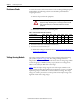
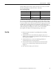
2. Measure DC resistance per the following chart:
Table 3 - Power Circuit Resistance Measurements
3. If abnormal readings are obtained, refer to Power Circuit Troubleshooting
on page 123 of Chapter 9.
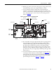
Voltage Sensing Module
The voltage-sensing module consists of a voltage sensing board and mounting
plate (refer to Figure 48 on page 120
). The voltage sensing board has six
independent channels, with different sized resistors base on voltage range, which
convert voltages up to 10800V (7.2 kV @ 1.5 pu) down to low voltage levels
which can be used by the SMC Flex control logic.
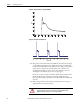
Tab l e 4
shows the input voltage ranges for each of the input terminals on the
voltage-sensing module. This module has been designed to operate at a nominal
input voltage of up to 7200V with a continuous 40% overvoltage. The output
voltages are scaled to provide close to 10V peak for a 140% input voltage at the
high end of each of the voltage ranges.
ATTENTION: Verify that all circuits are voltage free using a hot stick or
appropriate voltage measuring device. Severe injury or death can result
from electrical shock, burn, or unintended actuation of controlled
equipment.
Location of Probes 1000V 1300V 1500V 2300V 3300V 4160V 5500V 6900V
Cathode to Cathode (KOhms)
(1)
(1) Measured between terminals “Cathode” on CLGO Boards, upper two or between two within a phase.
----22-3023-3121-2924-32
Cathode to Cathode (KOhms)
(2)
(2) Measured between terminals “Cathode” on CLGO Boards, top to bottom within a phase.
17-23 19-25 20-27 21-29 40-53 43-57 60-90
(3)
(3) Measured between line and load terminals within a phase.
64-84
(3)
Cathode to Gate (Ohms) 10-40 10-40 10-40 10-40 10-40 10-40 10-40 10-40