
User guide

56 Rockwell Automation Publication 1560E-UM051F-EN-P - June 2013
Chapter 2 Installation
Control Terminal
Designations
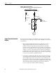
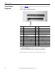
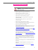
As shown in Figure 35, the SMC Flex controller contains 24 control terminals on
the front of the controller.
Figure 35 - SMC Flex Controller Control Terminals
Note: The OFF state leakage current for a solid-state device connected to an SMC Flex input must be less than 6 mA.
Terminal
Number
Description Terminal
Number
Description
11 Control Power Input
(1)
(1) RC snubbers are required on inductive loads connected to auxiliary.
23 PTC Input
(2)
12 Control Power Common
(1)
24 PTC Input
(2)
13 Control Enable Input
(2)
(2) Do not connect any additional loads to these terminals. These “parasitic” loads may cause problems with operation, which may
result in false starting and stopping.
25 Tach Input (-)
14 Control Module Ground 26 Tach Input (+)
15 Option Input #2
(1)(2)
27 Ground Fault Transformer Input
(2)
16 Option Input #1
(1)(2)
28 Ground Fault Transformer Input
(2)
17 Start Input
(1)(2)
29 Aux. Contact #2
(1)
18 Stop Input
(1)(2)
30 Aux. Contact #2
(1)
19 Aux. Contact #1 (Ext. Bypass)
(1)(3)
(3) Aux. Contact #1 is always programmed for Ext. Bypass (NO) to control the bypass contactor in MV applications.
31 Aux. Contact #3
(1)
20 Aux. Contact #1 (Ext. Bypass)
(1)(3)
32 Aux. Contact #3
(1)
21 Not Used 33 Aux. Contact #4 (Normal)
(1)(4)
(4) Aux Contact #4 is always programmed for “Normal” (NO) to control the isolation contactor in MV applications.
22 Not Used 34 Aux. Contact #4 (Normal)
(1)(4)