
User guide

Rockwell Automation Publication 1560E-UM051F-EN-P - June 2013 45
Installation Chapter 2
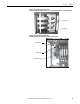
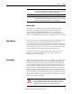
Figure 29 - Incoming Line Cable Connections
(viewed from the rear with power bus access cover removed) (Non Arc-resistant cabinet shown)
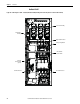
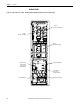
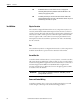
Figure 30 - Bottom Cable Exit Configuration
(with LV panel swung open) (Non Arc-resistant cabinet shown)
Power Cable Lugs
Ground Bus Lug
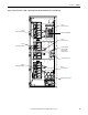
Cable Duct Boot
Cable Duct Barrier
Motor Cable Terminals