
User guide

18 Rockwell Automation Publication 1560E-UM051F-EN-P - June 2013
Chapter 1 Product Overview
Status Indication
All auxiliary contacts can be programmed as NO or NC for the following states
except External Bypass, which can only be programmed as NO.
Normal/Normal NC: The contact state changes when the unit receives a
Start/Stop signal
Up-to-Speed/Up-to-Speed NC: The contact state changes when the motor
approaches rated speed
Alarm/Alarm NC: The contact state changes when an Alarm condition is
detected
Fault/Fault NC: The contact state changes when a Fault condition is detected
Network Control/Network Control NC: The contact state is controlled over
the network. (Refer to Table 16 on page 109
, which describes logic command
word to control auxiliary outputs)
External Bypass: This contact controls the Bypass contactor for MV
applications.
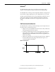
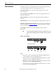
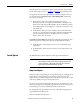
Figure 16 - Control Terminals
Note:
• The Aux #1 contact is always programmed for External Bypass (NO) to
control the bypass contactor in MV applications.
• The Aux #2 contact is typically programmed for fault indication in MV
applications (it can be configured for NO/NC).
• The Aux #3 contact is typically programmed for alarm indication in MV
applications (it can be configured for NO/NC).
• The Aux #4 contact is always configured as Normal (NO) to control the
line contactor for MV applications.
TIP
The tag name without a suffix indicates a NO state (e.g. Normal). On the other
hand, a tag name followed by NC indicates a normally closed state (e.g. Normal
NC).
11 12
13
14
15
16
17
18
19
20
21
23
24
25
26
27
28
29
30
31
32
33
34
22
a
SMC Flex Controller Terminals
Opt
Input
#2
Opt
Input
#1
Start
Input
Stop
Input
(External
Bypass)
Aux #1
PTC
Input
TACH
Input
Ground
Fault
(Fault
Contact)
Aux 2 Aux 3 Aux 4
(Alarm
Contact)
(Normal)