
User guide


Rockwell Automation Publication 1560E-UM051F-EN-P - June 2013 115
Troubleshooting Chapter 9
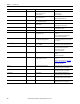
Table 18 - Fault Display Explanation
Display Fault Code Possible Causes Possible Solutions
Line Loss (with phase indication) 1, 2, 3 • Missing supply phase
• Motor not connected properly
• Improper or missing current or voltage
feedback
• Check for open line (e.g. blown line fuse)
• Check for open load lead
• Check current transformer connections and
module programming
• Check voltage sensing board connections and
module programming
• Check ribbon cable connections between
Interface Board and Control Module
• Check voltage feedback circuits
•Consult factory
Shorted SCR 4, 5 and 6 • Shorted Power Module • Check for shorted SCR, replace if necessary
(refer to Power Circuit Troubleshooting
on
page 123)
Open Gate (with phase indication) 7, 8 and 9 • Open gate circuitry
• Loose gate lead
• Perform power supply tests (Chapter 3
)
• Check gate lead connections to the gate driver
boards and fiber optics
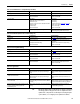
PTC Power Pole 10 • Controller ventilation blocked
• Controller duty cycle exceeded
•Fan failure
• Ambient temperature limit exceeded
• Failed thermistor
• Failed control module
• Failed gate driver board
• Failed fiber optic cable
• Failed interface board
• Check for proper ventilation
• Check application duty cycle
•Replace fan
• Wait for controller to cool or provide external
cooling
• Check connection or replace thermistor
• Replace control module
• Test or replace gate driver board
• Test or replace cable
• Test or replace interface board; check ribbon
cables
Motor PTC 12 • Motor ventilation blocked
• Motor duty cycle exceeded
•PTC open
• Check for proper ventilation
• Check application duty cycle
• Wait for motor to cool or provide external
cooling
• Check resistance of PTC
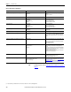
Open Bypass 13, 14, 15 • Control voltage is low
• Inoperable bypass contactor
•IntelliVAC fault
• Check control voltage power supply
• Check control circuit operation
• Check control plug on contactor
• Check status of IntelliVAC, correct the condition,
reset the module
No load 16, 17, 18, 40 • Loss of load side power wiring
• Loss of feedback
• Check all load side power connections and
motor windings
• Check voltage sensing module
Line Unbalance 19 • Supply unbalance is greater than the user-
programmed value
• The delay time is too short for the application
• Unbalanced feedback
• Check power system and correct if necessary
• Extend the delay time to match the application
requirements
• Check voltage sensing module
Overvoltage 20 • Supply voltage is greater than user-
programmed value
• Check power system and correct if necessary
• Correct the user-programmed value
Undervoltage 21 • Supply voltage is less than user-programmed
value
• The delay time is too short for the application
• Check power system and correct if necessary
• Correct the user-programmed value
• Extend the delay time to match the application
requirements.
Overload 22 • Motor overloaded
• Overload parameters are not matched to the
motor
• Check motor overload condition
• Check programmed values for overload class
and motor FLC