
Configuration and Diagnostic Software Tool User Manual Owner manual
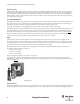
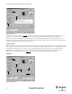
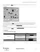

Table Of Contents
- Content
- 1. Introduction
- 2. Installation
- 3. Optical Interface
- 4. Configuration Tool for GuardShield Safe 2/Safe 4 Light Curtains
- 5. Configuration Tool for MSR42
- 5.1. Introduction
- 5.2. Starting MSR42 Configuration Tool
- 5.3. The menu bar
- 5.4. Main window
- 5.4.1. Tab “Design”
- 5.4.2. Tab “Diagnosis”
- 5.4.3. Tab “Application info”
- 5.4.4. Possible Configurations
- 5.4.5. Micro 400 Light Curtain
- 5.4.6. One Device (2 NC)
- 5.4.7. One or Two Device (OSSDs)
- 5.4.8. Safety override
- 5.4.9. Muting Micro 400
- 5.4.10. Muting other device (OSSDs)
- 5.4.11. Function “EDM” + “Start Release”
- 5.4.12. Function “Stop delay”
- 5.5. Download, Verify & Upload
- 5.6. Muting
- 5.6.1. General
- 5.6.2. Muting lamp
- 5.6.3. Muting sensors
- 5.6.4. Mute dependant override function
- 5.6.5. Sensor output delay function
- 5.6.6. Muting with enable signal
- 5.6.7. Muting disable function
- 5.6.8. Safety light curtain interruption monitoring function
- 5.6.9. 43BMuting time recorder
- 5.6.10. 44BSetup: 2 sensor T-type
- 5.6.11. Setup: four sensor T-type
- 5.6.12. Setup: two sensor L-type
- 5.6.13. Setup: two sensor T-type with enable signal
- 5.7. Blanking
- 6. Appendix

53
Light Curtain Multi-Function Control Module User Manual
Original instructions
5.7.4. Combining Blanking modes
The protective field of a single Micro 400 light curtain may be split up and configured into different regions. From a safety technical point of view, it is
especially critical that the resolution is inspected at the cross over point from one protective field region to the next, as well as the borders or edges of
each region. The MSR42 Configuration Tool takes into account these cross over areas when calculating the resolution and provides, as a result, the
largest (resolution) for the complete light curtain system.
5.7.5. Indication of Blanking
If Blanking is configured then a lamp must clearly indicate this to the operator. The MSR42 Basic Configuration unit monitors the connection of a
Blanking lamp. If this lamp is defective or not connected, the MSR42 controller will immediately cancel the blanking function and return to the
standard safety mode (see also: MSR42 user manual).
However, depending on the risk analysis of the application, the monitoring of the indication lamp may be deactivated (#6 Figure 74
). Even when
deactivated, a connected lamp will still function if blanking is configured, but it will no longer be monitored.
Hint: for teach-in blanking a lamp is always required.
Important safety notice:
The Blanking lamp must be mounted near the protective field, clearly visible to the operator.
5.7.6. Activating blanking
The descriptions above explain in detail what the differences are between the three Blanking modes.
•Fixed Blanking
• Floating Blanking
• Teach-in Blanking
Fixed blanking and Floating blanking can be activated by downloading the configuration into the MSR42 controller. Teach-in blanking can be activated
with the Basic Configuration (See chapter 5.4.1.2 on page 20)
, or by downloading a configuration with this function active into the MSR42 controller.
The light curtain protective field may be divided into one to three different regions, whereby each region may be configured independently with Fixed
or Floating blanking. Teach-in blanking may only be used for one region: the entire light curtain protective field. When using Teach-in blanking, one or
two different objects may be detected and blanked.
Important safety notice:
The configuration of Blanking will lead to longer reaction times, and possibly also to higher resolutions. These changes must be taken into account
when calculating the minimum safety distance. The new response time, as well as a possible new resolution, will be shown in the Configuration Control
Document.
Important safety notice:
After the Blanking configuration has been carried out, the user is responsible for testing the resolution of the light curtain. The blanked region should
be clearly marked, and the protective field should be fully tested with test rods according to the instructions given in the Micro 400 user manual.
5.7.7. Configuring the Blanking Function
The blanking function is accessed from the Micro 400 window by selecting the blanking ‘Edit’ button (Figure 33).