
Configuration and Diagnostic Software Tool User Manual Owner manual
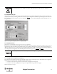
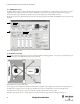
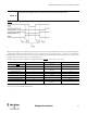
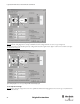
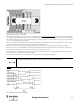
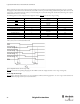
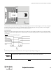
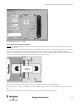
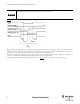
Table Of Contents
- Content
- 1. Introduction
- 2. Installation
- 3. Optical Interface
- 4. Configuration Tool for GuardShield Safe 2/Safe 4 Light Curtains
- 5. Configuration Tool for MSR42
- 5.1. Introduction
- 5.2. Starting MSR42 Configuration Tool
- 5.3. The menu bar
- 5.4. Main window
- 5.4.1. Tab “Design”
- 5.4.2. Tab “Diagnosis”
- 5.4.3. Tab “Application info”
- 5.4.4. Possible Configurations
- 5.4.5. Micro 400 Light Curtain
- 5.4.6. One Device (2 NC)
- 5.4.7. One or Two Device (OSSDs)
- 5.4.8. Safety override
- 5.4.9. Muting Micro 400
- 5.4.10. Muting other device (OSSDs)
- 5.4.11. Function “EDM” + “Start Release”
- 5.4.12. Function “Stop delay”
- 5.5. Download, Verify & Upload
- 5.6. Muting
- 5.6.1. General
- 5.6.2. Muting lamp
- 5.6.3. Muting sensors
- 5.6.4. Mute dependant override function
- 5.6.5. Sensor output delay function
- 5.6.6. Muting with enable signal
- 5.6.7. Muting disable function
- 5.6.8. Safety light curtain interruption monitoring function
- 5.6.9. 43BMuting time recorder
- 5.6.10. 44BSetup: 2 sensor T-type
- 5.6.11. Setup: four sensor T-type
- 5.6.12. Setup: two sensor L-type
- 5.6.13. Setup: two sensor T-type with enable signal
- 5.7. Blanking
- 6. Appendix
44
Light Curtain Multi-Function Control Module User Manual
Original instructions
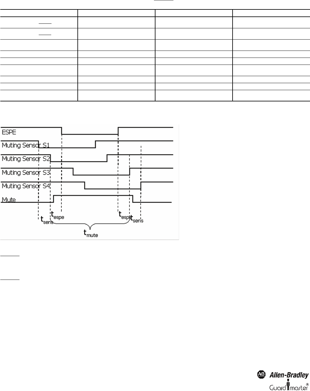
Muting of the Micro 400 light curtain is achieved only when muting sensor S1 and S2 are activated within the specified time t(sens). For a successful
muting sequence all four sensors must be simultaneously activated for a certain time period. The muting condition will stop when either sensor S3 or S4
is deactivated, or the maximal muting time t(mute) is exceeded (muting time out). Since this muting mode is bidirectional, the muting sensor sequence
will also function in reverse (i.e. S4 =>S1).
The following parameters can be configured in the configuration window (Figure 62
) for “four sensor T-type” muting.
Table 2 (* = a setting smaller or close to the total response time may influence the stability of the muting system)
A time t(sense) of 4 s is recommended in IEC 62046
Figure 62: Configuration window for “four sensor T-type” muting
Figure 62
also shows the corresponding wiring diagram of the MSR42 control unit configured with the “4 sensor T-type” muting mode.
5.6.12. Setup: two sensor L-type
Figure 63 shows a schematic arrangement for a two sensor, parallel beam, unidirectional muting application: “two sensor L-type.” Either the Micro 400
or a GuardShield safety light curtain may be muted in this manner.
Parameter Standard Value Max./Min. Values Possible Settings
T(sense) [Figure 57]4 s
Min.: 50 ms
Max.: 10 s
Min.: N x 0.05 s
T(mute) [Figure 57]5 min
Min.: 0 s
Max.: 10 days
(*)
T(msdel) [5.6.5] 50 ms
Min.: 0 ms
Max.: 2.55 s
N x 0.01 s
Muting lamp monitoring [5.6.2] yes yes/no
Mute dependant override [5.6.4] yes yes / no
T(mdo) [5.6.4] 5 s
Min.: 0 ms
Max.: 20 min
N x 5 s
Mute disable signal [5.6.7] no yes / no
Micro 400 interruption monitoring [5.6.8] no yes / no
T(espe) [5.6.8] 5 s
Min.: 0 s
Max.: 10 s
N x 0.05 s (*)