
Configuration and Diagnostic Software Tool User Manual Owner manual
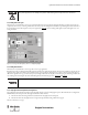
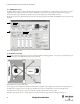
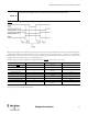
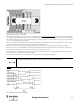
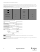
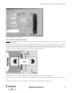
Table Of Contents
- Content
- 1. Introduction
- 2. Installation
- 3. Optical Interface
- 4. Configuration Tool for GuardShield Safe 2/Safe 4 Light Curtains
- 5. Configuration Tool for MSR42
- 5.1. Introduction
- 5.2. Starting MSR42 Configuration Tool
- 5.3. The menu bar
- 5.4. Main window
- 5.4.1. Tab “Design”
- 5.4.2. Tab “Diagnosis”
- 5.4.3. Tab “Application info”
- 5.4.4. Possible Configurations
- 5.4.5. Micro 400 Light Curtain
- 5.4.6. One Device (2 NC)
- 5.4.7. One or Two Device (OSSDs)
- 5.4.8. Safety override
- 5.4.9. Muting Micro 400
- 5.4.10. Muting other device (OSSDs)
- 5.4.11. Function “EDM” + “Start Release”
- 5.4.12. Function “Stop delay”
- 5.5. Download, Verify & Upload
- 5.6. Muting
- 5.6.1. General
- 5.6.2. Muting lamp
- 5.6.3. Muting sensors
- 5.6.4. Mute dependant override function
- 5.6.5. Sensor output delay function
- 5.6.6. Muting with enable signal
- 5.6.7. Muting disable function
- 5.6.8. Safety light curtain interruption monitoring function
- 5.6.9. 43BMuting time recorder
- 5.6.10. 44BSetup: 2 sensor T-type
- 5.6.11. Setup: four sensor T-type
- 5.6.12. Setup: two sensor L-type
- 5.6.13. Setup: two sensor T-type with enable signal
- 5.7. Blanking
- 6. Appendix
43
Light Curtain Multi-Function Control Module User Manual
Original instructions
Figure 60: Example, “four sensor (S1 - S4), T-type” muting
This muting mode is similar to the “two sensor, T-type w/enable signal” muting (See chapter 5.6.6 on page 39)
, and should also be considered when the
size and position of the pallet load is irregular, or the size of the pallet is much smaller than the width of the conveyor. Due to the two sensor input from
either side of the light curtain, however an external enable signal (e.g. conveyor run signal) is not necessary. This mode may require more space than the
“two sensor T-type w/enable signal” muting mode.
Sensors two and three (closest to the light curtain) should be mounted within 200 mm of the light curtain so that it is difficult for a person to enter the
dangerous zone undetected by preceding or following a load system into the dangerous zone.
The distance between any two muting sensors must be greater than 250 mm so that they cannot be activated simultaneously by a person’s leg.
The distance between sensor S1 and S4 shall be such that a cylindrical object with a diameter of 500 mm with its axis parallel to the protective field
cannot activate the muting function when moved in any point of the gate at any speed up to 1.6 m/s.
The muting sensors S1 – S4 should detect the objects on pallets and not the pallet itself. When this is impractical additional measures may be necessary
to prevent people from entering the zone by sitting on the pallet.
It should not be possible for a person to pass undetected to the left or right of the object during the muting process.
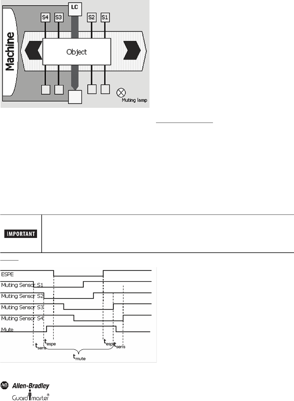
Figure 61
shows the corresponding timing sequence for such an arrangement.
Figure 61: Timing sequence for “four sensor, T-type” muting
A detailed description about muting, muting restrictions as well as hints for the installation are given in the
standard IEC 62046. Additional hints are mentioned in the attachment A7 of IEC 61496-1.