
Configuration and Diagnostic Software Tool User Manual Owner manual
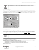
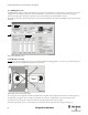
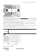
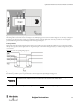
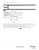
Table Of Contents
- Content
- 1. Introduction
- 2. Installation
- 3. Optical Interface
- 4. Configuration Tool for GuardShield Safe 2/Safe 4 Light Curtains
- 5. Configuration Tool for MSR42
- 5.1. Introduction
- 5.2. Starting MSR42 Configuration Tool
- 5.3. The menu bar
- 5.4. Main window
- 5.4.1. Tab “Design”
- 5.4.2. Tab “Diagnosis”
- 5.4.3. Tab “Application info”
- 5.4.4. Possible Configurations
- 5.4.5. Micro 400 Light Curtain
- 5.4.6. One Device (2 NC)
- 5.4.7. One or Two Device (OSSDs)
- 5.4.8. Safety override
- 5.4.9. Muting Micro 400
- 5.4.10. Muting other device (OSSDs)
- 5.4.11. Function “EDM” + “Start Release”
- 5.4.12. Function “Stop delay”
- 5.5. Download, Verify & Upload
- 5.6. Muting
- 5.6.1. General
- 5.6.2. Muting lamp
- 5.6.3. Muting sensors
- 5.6.4. Mute dependant override function
- 5.6.5. Sensor output delay function
- 5.6.6. Muting with enable signal
- 5.6.7. Muting disable function
- 5.6.8. Safety light curtain interruption monitoring function
- 5.6.9. 43BMuting time recorder
- 5.6.10. 44BSetup: 2 sensor T-type
- 5.6.11. Setup: four sensor T-type
- 5.6.12. Setup: two sensor L-type
- 5.6.13. Setup: two sensor T-type with enable signal
- 5.7. Blanking
- 6. Appendix
40
Light Curtain Multi-Function Control Module User Manual
Original instructions
5.6.9. 43BMuting time recorder
The MSR42 offers the ability to configure many different timing sequences. During installation of a complete muting system it is often not clear what
configured time values will guarantee trouble free operation. Small variations (e.g. in object size) may lead to unnecessary machine stoppage. To
determine the timing of a given installation it is possible to measure the real timing sequence with the MSR42 control unit.
Based on these measurements, optimized timing values can be selected so that the application runs reliably, while fulfilling the safety requirements of the
risk analysis.
Figure 55: Tab sheet “Muting time recorder”
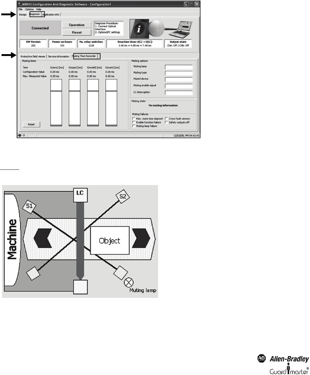
5.6.10. 44BSetup: 2 sensor T-type
Figure 56 shows a schematic arrangement for a two sensor, crossed beam, bidirectional muting application: “two sensor T-type.” For this muting mode
either the Micro 400 or the GuardShield safety light curtains may be muted.
Figure 56: Example, “Two sensor (S1 and S2) T-type” muting
The crossing point of the two light beams should be situated behind the sensing field of the safety light curtain in the direction of the dangerous area.
The height of the crossing point of the two muting sensors should be at the same level as or higher than the lowest beam of the light curtain.
The distance from the crossing point to the protective field of the safety light curtain should be as short as possible.
It should not be possible for a person to enter the dangerous area undetected to the left or right of the object during the muting process.