
Configuration and Diagnostic Software Tool User Manual Owner manual
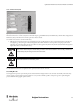
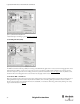
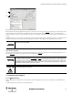
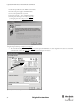
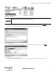
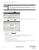
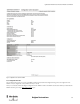
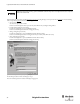
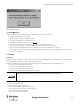
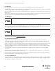
Table Of Contents
- Content
- 1. Introduction
- 2. Installation
- 3. Optical Interface
- 4. Configuration Tool for GuardShield Safe 2/Safe 4 Light Curtains
- 5. Configuration Tool for MSR42
- 5.1. Introduction
- 5.2. Starting MSR42 Configuration Tool
- 5.3. The menu bar
- 5.4. Main window
- 5.4.1. Tab “Design”
- 5.4.2. Tab “Diagnosis”
- 5.4.3. Tab “Application info”
- 5.4.4. Possible Configurations
- 5.4.5. Micro 400 Light Curtain
- 5.4.6. One Device (2 NC)
- 5.4.7. One or Two Device (OSSDs)
- 5.4.8. Safety override
- 5.4.9. Muting Micro 400
- 5.4.10. Muting other device (OSSDs)
- 5.4.11. Function “EDM” + “Start Release”
- 5.4.12. Function “Stop delay”
- 5.5. Download, Verify & Upload
- 5.6. Muting
- 5.6.1. General
- 5.6.2. Muting lamp
- 5.6.3. Muting sensors
- 5.6.4. Mute dependant override function
- 5.6.5. Sensor output delay function
- 5.6.6. Muting with enable signal
- 5.6.7. Muting disable function
- 5.6.8. Safety light curtain interruption monitoring function
- 5.6.9. 43BMuting time recorder
- 5.6.10. 44BSetup: 2 sensor T-type
- 5.6.11. Setup: four sensor T-type
- 5.6.12. Setup: two sensor L-type
- 5.6.13. Setup: two sensor T-type with enable signal
- 5.7. Blanking
- 6. Appendix
33
Light Curtain Multi-Function Control Module User Manual
Original instructions
Figure 46: Device no. printed on label
8. A window will appear, which shows the process of the communication from the PC to the MSR42 control module (Figure 47).
9. Now reconnect the +24V DC power supply to the MSR42 control module, and the data transmission will begin.
Figure 47: Communication PC to MSR42
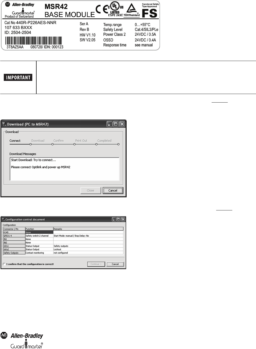
10. After the download has started, the window “Configuration control document” window will appear on your monitor (Figure 48
).
Figure 48: Control document
11. Review the configuration data in this window!
12. Check the control box to confirm the configuration is correct. After this confirmation the “Continue” Button will be enabled
The device number and designation must be entered. These inputs are later shown on the configuration
control document and guarantees the product identification.