
Configuration and Diagnostic Software Tool User Manual Owner manual
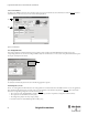
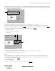
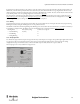
Table Of Contents
- Content
- 1. Introduction
- 2. Installation
- 3. Optical Interface
- 4. Configuration Tool for GuardShield Safe 2/Safe 4 Light Curtains
- 5. Configuration Tool for MSR42
- 5.1. Introduction
- 5.2. Starting MSR42 Configuration Tool
- 5.3. The menu bar
- 5.4. Main window
- 5.4.1. Tab “Design”
- 5.4.2. Tab “Diagnosis”
- 5.4.3. Tab “Application info”
- 5.4.4. Possible Configurations
- 5.4.5. Micro 400 Light Curtain
- 5.4.6. One Device (2 NC)
- 5.4.7. One or Two Device (OSSDs)
- 5.4.8. Safety override
- 5.4.9. Muting Micro 400
- 5.4.10. Muting other device (OSSDs)
- 5.4.11. Function “EDM” + “Start Release”
- 5.4.12. Function “Stop delay”
- 5.5. Download, Verify & Upload
- 5.6. Muting
- 5.6.1. General
- 5.6.2. Muting lamp
- 5.6.3. Muting sensors
- 5.6.4. Mute dependant override function
- 5.6.5. Sensor output delay function
- 5.6.6. Muting with enable signal
- 5.6.7. Muting disable function
- 5.6.8. Safety light curtain interruption monitoring function
- 5.6.9. 43BMuting time recorder
- 5.6.10. 44BSetup: 2 sensor T-type
- 5.6.11. Setup: four sensor T-type
- 5.6.12. Setup: two sensor L-type
- 5.6.13. Setup: two sensor T-type with enable signal
- 5.7. Blanking
- 6. Appendix
24
Light Curtain Multi-Function Control Module User Manual
Original instructions
Chapter Function. . . . . . . . . . . . . . . . . . . . . . . . . . . . . . . . . . . . . . . . . . . . . . . . . . . . . . . . . . . . . . . . Page
5.4.5 Micro 400 Light Curtain. . . . . . . . . . . . . . . . . . . . . . . . . . . . . . . . . . . . . . . . . . . . . . . . . . . . 35
5.4.5.1 Blanking . . . . . . . . . . . . . . . . . . . . . . . . . . . . . . . . . . . . . . . . . . . . . . . . . . . . . . . . . . . . . . . . . . . . . . . . . . . . . . . . . . . . . . 36
5.4.5.2 Interrupt Ignore Time . . . . . . . . . . . . . . . . . . . . . . . . . . . . . . . . . . . . . . . . . . . . . . . . . . . . . . . . . . . . . . . . . . . . . . . . . . 37
5.4.5.3 Double Scan Filter. . . . . . . . . . . . . . . . . . . . . . . . . . . . . . . . . . . . . . . . . . . . . . . . . . . . . . . . . . . . . . . . . . . . . . . . . . . . . . 38
5.4.6 One Device (2 NC) . . . . . . . . . . . . . . . . . . . . . . . . . . . . . . . . . . . . . . . . . . . . . . . . . . . . . . . . . 39
5.4.7 One or Two Device (OSSDs) . . . . . . . . . . . . . . . . . . . . . . . . . . . . . . . . . . . . . . . . . . . . . . . . 39
5.4.8 Safety override . . . . . . . . . . . . . . . . . . . . . . . . . . . . . . . . . . . . . . . . . . . . . . . . . . . . . . . . . . . 40
5.4.8.1 Override Micro 400 Safety light curtain . . . . . . . . . . . . . . . . . . . . . . . . . . . . . . . . . . . . . . . . . . . . . . . . . . . . . . . . . . 41
5.4.8.2 Override One Device (OSSD). . . . . . . . . . . . . . . . . . . . . . . . . . . . . . . . . . . . . . . . . . . . . . . . . . . . . . . . . . . . . . . . . . . 42
5.4.9 Muting Micro 400 . . . . . . . . . . . . . . . . . . . . . . . . . . . . . . . . . . . . . . . . . . . . . . . . . . . . . . . . . 43
5.4.10 Muting other device (OSSDs). . . . . . . . . . . . . . . . . . . . . . . . . . . . . . . . . . . . . . . . . . . . . . . 44
Generally the individual specification windows for the safety components are structured the same way: should a stop delay be active and what kind of
start mode should be activated.
Detailed settings or functions can be done in the individual specification windows. These windows pop up after selecting the function or at a later point
in time by clicking on the “Edit” button (4, Figure 25
).
Furthermore under “Safety Outputs OSSD” the functions “External Device Monitoring” (EDM) and “Start Release” as well as “Stop delay” can be
configured (3, Figure 25
):
Chapter Function . . . . . . . . . . . . . . . . . . . . . . . . . . . . . . . . . . . . . . . . . . . . . . . . . . . . . . . . . . . . . . .Page
5.4.11 “EDM” + “Start release” . . . . . . . . . . . . . . . . . . . . . . . . . . . . . . . . . . . . . . . . . . . . . . . . . . . 44
5.4.12 “Stop delay” . . . . . . . . . . . . . . . . . . . . . . . . . . . . . . . . . . . . . . . . . . . . . . . . . . . . . . . . . . . . . . 45
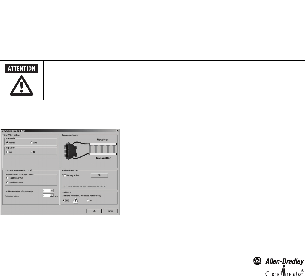
5.4.5. Micro 400 Light Curtain
In order to configure a Micro 400 light curtain, the input specification window “Micro 400 Light Curtain” must be selected (1 and 4 Figure 25).
Figure 33: Specification window “Micro 400 Light Curtain”
The corresponding start mode and if required the stop delay function must be selected. The stop delay time itself is defined in the “Safety Output
OSSD” window (See chapter 5.4.12 on page 31)
When configuring the start mode and/or using the “Safety override switch,” the general safety notices found
in the MSR42 user manual must be followed!