
Configuration and Diagnostic Software Tool User Manual Owner manual
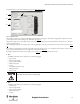
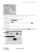
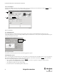
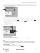
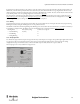
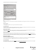
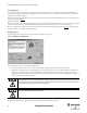
Table Of Contents
- Content
- 1. Introduction
- 2. Installation
- 3. Optical Interface
- 4. Configuration Tool for GuardShield Safe 2/Safe 4 Light Curtains
- 5. Configuration Tool for MSR42
- 5.1. Introduction
- 5.2. Starting MSR42 Configuration Tool
- 5.3. The menu bar
- 5.4. Main window
- 5.4.1. Tab “Design”
- 5.4.2. Tab “Diagnosis”
- 5.4.3. Tab “Application info”
- 5.4.4. Possible Configurations
- 5.4.5. Micro 400 Light Curtain
- 5.4.6. One Device (2 NC)
- 5.4.7. One or Two Device (OSSDs)
- 5.4.8. Safety override
- 5.4.9. Muting Micro 400
- 5.4.10. Muting other device (OSSDs)
- 5.4.11. Function “EDM” + “Start Release”
- 5.4.12. Function “Stop delay”
- 5.5. Download, Verify & Upload
- 5.6. Muting
- 5.6.1. General
- 5.6.2. Muting lamp
- 5.6.3. Muting sensors
- 5.6.4. Mute dependant override function
- 5.6.5. Sensor output delay function
- 5.6.6. Muting with enable signal
- 5.6.7. Muting disable function
- 5.6.8. Safety light curtain interruption monitoring function
- 5.6.9. 43BMuting time recorder
- 5.6.10. 44BSetup: 2 sensor T-type
- 5.6.11. Setup: four sensor T-type
- 5.6.12. Setup: two sensor L-type
- 5.6.13. Setup: two sensor T-type with enable signal
- 5.7. Blanking
- 6. Appendix
21
Light Curtain Multi-Function Control Module User Manual
Original instructions
Figure 27: Basic configuration
In this window eight different wiring options of the “Basic configuration” can be displayed. These options can be realized just by wiring any standard,
out of the box MSR42 control unit (Cat. # 440R-P226AGS-NNR). No additional configuration is necessary.
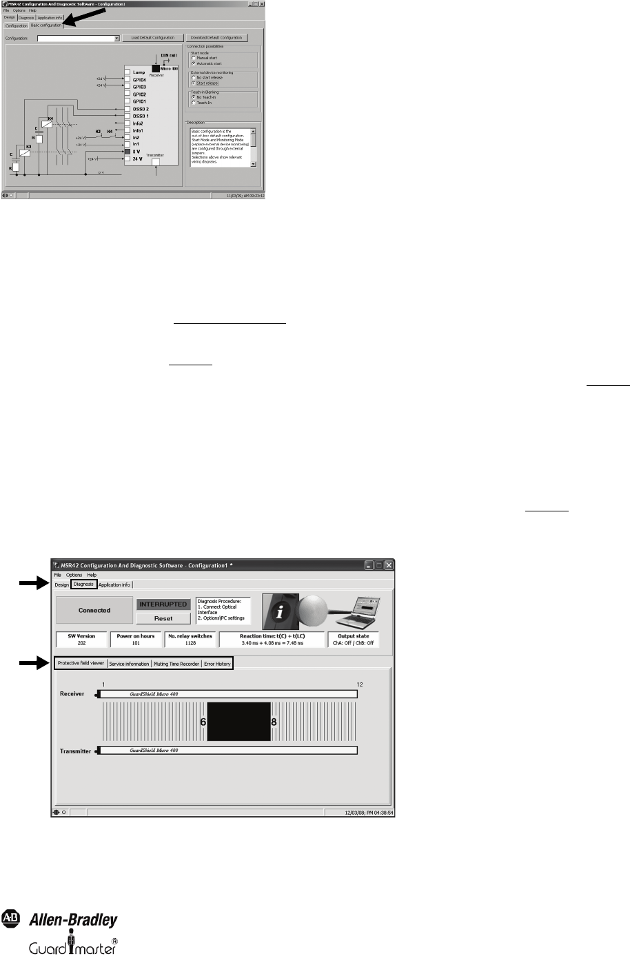
5.4.2. Tab “Diagnosis”
In order to carry out a diagnostic of a MSR42 control unit, the following steps must be made:
1. Connect the Optical Interface (See chapter 3 on page 8)
, to the PC and the MSR42
1. Start the MSR42 “Configuration and diagnostic Software” Tool
3. Select the “Diagnosis” tab (1, Figure 28
)
The program immediately detects the MSR42 and displays the transmitted data. Three different functions may be selected (2, Figure 28
):
• Protective field viewer
•Service information
• Muting time recorder
Switch between these functions by choosing the corresponding sub-tab.
5.4.2.1. Protective field viewer
This function graphically shows the interrupted area of the GuardShield Micro 400 light curtain protective field (Figure 28
). The numbers displayed in
this window represent the first and the last interrupted beams. No definite statement can be made with regards to the status of the beams between these
two beams, since this information is not transmitted to the MSR42 Configuration and Diagnostic Software.
Figure 28: Example of a protective field interruption
1
2