
Configuration and Diagnostic Software Tool User Manual Owner manual
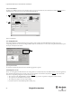
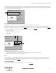
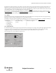
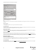
Table Of Contents
- Content
- 1. Introduction
- 2. Installation
- 3. Optical Interface
- 4. Configuration Tool for GuardShield Safe 2/Safe 4 Light Curtains
- 5. Configuration Tool for MSR42
- 5.1. Introduction
- 5.2. Starting MSR42 Configuration Tool
- 5.3. The menu bar
- 5.4. Main window
- 5.4.1. Tab “Design”
- 5.4.2. Tab “Diagnosis”
- 5.4.3. Tab “Application info”
- 5.4.4. Possible Configurations
- 5.4.5. Micro 400 Light Curtain
- 5.4.6. One Device (2 NC)
- 5.4.7. One or Two Device (OSSDs)
- 5.4.8. Safety override
- 5.4.9. Muting Micro 400
- 5.4.10. Muting other device (OSSDs)
- 5.4.11. Function “EDM” + “Start Release”
- 5.4.12. Function “Stop delay”
- 5.5. Download, Verify & Upload
- 5.6. Muting
- 5.6.1. General
- 5.6.2. Muting lamp
- 5.6.3. Muting sensors
- 5.6.4. Mute dependant override function
- 5.6.5. Sensor output delay function
- 5.6.6. Muting with enable signal
- 5.6.7. Muting disable function
- 5.6.8. Safety light curtain interruption monitoring function
- 5.6.9. 43BMuting time recorder
- 5.6.10. 44BSetup: 2 sensor T-type
- 5.6.11. Setup: four sensor T-type
- 5.6.12. Setup: two sensor L-type
- 5.6.13. Setup: two sensor T-type with enable signal
- 5.7. Blanking
- 6. Appendix
19
Light Curtain Multi-Function Control Module User Manual
Original instructions
Detailed information on the various configurations are given in chapter 5.4.4 on page 23
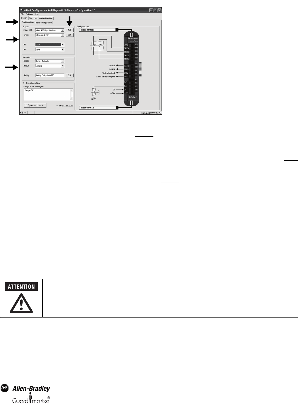
Figure 25: Configuration window
After selecting a component or a function, an individual specification window will pop up to allow further setting adjustments. Adjustments at a later
point in time may also be made by clicking on the “Edit” button (4, Figure 25
).
All specification windows are set up similarly. They show the connection terminals, give important safety information, and allow the user to change all
important configuration data.
After configuring the Input data the “Design Output” area shows graphically how the safety component must be connected to the control unit (Figure
25).
If an exclamation symbol is displayed to the left of the OSSD outputs in the “Design Output” area, a stop delay has been activated for at least one of the
safety components. Details will be sown on the configuration control document (Figure 51
)
By clicking on the pull-down windows in the “Outputs” section (3, Figure 25
) the following options may be selected:
AInfo 1
The MSR42 terminal Info 1 can be allocated to any of the following signals.
•Safety Outputs
• Micro 400 Light Curtain
• Safety Component (GPIO)
•EDM or Start Release
•Lockout
• Low Light Intensity (Micro 400)
• Muting (Automatic)
•Safety Override
BInfo 2
The MSR42 terminal Info 2 can be allocated to any of the following signals.
•Safety Outputs
• Micro 400 Light Curtain
• Safety Component (GPIO)
•EDM or Start Release
•Lockout
1
2
3
4
The info output is status information only.
The output may not be used as a safety signal!