
Configuration and Diagnostic Software Tool User Manual Owner manual
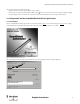
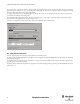
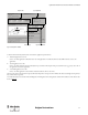
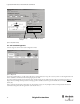
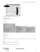
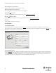
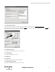
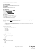
Table Of Contents
- Content
- 1. Introduction
- 2. Installation
- 3. Optical Interface
- 4. Configuration Tool for GuardShield Safe 2/Safe 4 Light Curtains
- 5. Configuration Tool for MSR42
- 5.1. Introduction
- 5.2. Starting MSR42 Configuration Tool
- 5.3. The menu bar
- 5.4. Main window
- 5.4.1. Tab “Design”
- 5.4.2. Tab “Diagnosis”
- 5.4.3. Tab “Application info”
- 5.4.4. Possible Configurations
- 5.4.5. Micro 400 Light Curtain
- 5.4.6. One Device (2 NC)
- 5.4.7. One or Two Device (OSSDs)
- 5.4.8. Safety override
- 5.4.9. Muting Micro 400
- 5.4.10. Muting other device (OSSDs)
- 5.4.11. Function “EDM” + “Start Release”
- 5.4.12. Function “Stop delay”
- 5.5. Download, Verify & Upload
- 5.6. Muting
- 5.6.1. General
- 5.6.2. Muting lamp
- 5.6.3. Muting sensors
- 5.6.4. Mute dependant override function
- 5.6.5. Sensor output delay function
- 5.6.6. Muting with enable signal
- 5.6.7. Muting disable function
- 5.6.8. Safety light curtain interruption monitoring function
- 5.6.9. 43BMuting time recorder
- 5.6.10. 44BSetup: 2 sensor T-type
- 5.6.11. Setup: four sensor T-type
- 5.6.12. Setup: two sensor L-type
- 5.6.13. Setup: two sensor T-type with enable signal
- 5.7. Blanking
- 6. Appendix

18
Light Curtain Multi-Function Control Module User Manual
Original instructions
5.3.3.3. Menu “Safety information”
Gives important safety information for installing and operating the software.
5.3.3.4. Menu “About”
Displays the welcome window to check software version.
5.4. Main window
Three main tabs are available to choose from (Figure 20):
1. Design (See chapter 5.4.1 on page 18)
2. Diagnosis (See chapter 5.4.2 on page 21)
3. Application info (See chapter 5.4.3 on page 22)
5.4.1. Tab “Design”
In the design window two sub-tabs are available (1, Figure 25):
1. Configuration (See chapter 5.4.1.1 on page 18)
2. Basic configuration (See chapter 5.4.1.2 on page 20)
5.4.1.1. Configuration
This tab offers the possibility to specify the type and the properties of the safety components that can be controlled. By clicking on the pull-down
windows in the area “Inputs” (2, Figure 25
) the following options may be selected:
A Micro 400
•None
An MSR42 control unit can also be used for safety functions without a Micro 400 safety light curtain (for example E-Stop, Door-Switch,
overriding of a safety device, muting of a safety device, time delay.)
• Micro 400 light curtain
B GPIO (General Purpose Input / Output
Which signal is connected to the GPIO1 to GPIO4 pins.
•None
• 1 Device (2NC)
• 1 Device (OSSDs)
• 2 Device (OSSDs)
•Override Micro 400
• Override 1 Device (OSSD)
•Muting Micro 400
• Muting other devices (OSSD)
CInput IN1
Which signal is connected to the input IN1
•Test Input
•Start
•None
DInput IN2
Which signal is connected to the input IN2
•Start
•EDM
•Start Release
•None