
Configuration and Diagnostic Software Tool User Manual Owner manual
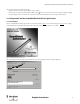
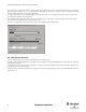
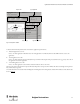
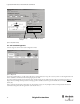
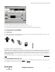
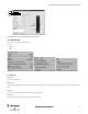
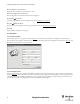
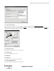
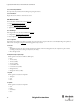
Table Of Contents
- Content
- 1. Introduction
- 2. Installation
- 3. Optical Interface
- 4. Configuration Tool for GuardShield Safe 2/Safe 4 Light Curtains
- 5. Configuration Tool for MSR42
- 5.1. Introduction
- 5.2. Starting MSR42 Configuration Tool
- 5.3. The menu bar
- 5.4. Main window
- 5.4.1. Tab “Design”
- 5.4.2. Tab “Diagnosis”
- 5.4.3. Tab “Application info”
- 5.4.4. Possible Configurations
- 5.4.5. Micro 400 Light Curtain
- 5.4.6. One Device (2 NC)
- 5.4.7. One or Two Device (OSSDs)
- 5.4.8. Safety override
- 5.4.9. Muting Micro 400
- 5.4.10. Muting other device (OSSDs)
- 5.4.11. Function “EDM” + “Start Release”
- 5.4.12. Function “Stop delay”
- 5.5. Download, Verify & Upload
- 5.6. Muting
- 5.6.1. General
- 5.6.2. Muting lamp
- 5.6.3. Muting sensors
- 5.6.4. Mute dependant override function
- 5.6.5. Sensor output delay function
- 5.6.6. Muting with enable signal
- 5.6.7. Muting disable function
- 5.6.8. Safety light curtain interruption monitoring function
- 5.6.9. 43BMuting time recorder
- 5.6.10. 44BSetup: 2 sensor T-type
- 5.6.11. Setup: four sensor T-type
- 5.6.12. Setup: two sensor L-type
- 5.6.13. Setup: two sensor T-type with enable signal
- 5.7. Blanking
- 6. Appendix

10
Light Curtain Multi-Function Control Module User Manual
Original instructions
The “system designer” is split into two sections, a “Designer’s Input” and “Designer’s Output” section. The “Designer’s input” section is used to define a
light curtain: pair or transmitter or receiver, as well as the protective field height and resolution. The “Designers Output” section displays the resulting
information and catalog number for the configured light curtain.
To configure a light curtain stay in the Graphical Designer tab. Place the mouse cursor on each input base, press the left mouse button and a list will
appear with all the available choices for that position.
Upon completion of the configuration selections, the light curtain catalog number, safety category, response time, height/resolution and operating
range information will be displayed in the “Designer’s Output” section.
To design a new configuration, press the “Reset” button. To print the configuration, press the “Print” button.
Figure 13: Configured Safe 4 Light Curtain example
4.2. Safety Distance Calculator
Select the “Application Info” tab to display the minimal safety distance calculation section.
The display is usable for the GuardShield Safe 2/Safe 4 light curtains. For applications with the GuardShield Micro 400 Light Curtains, use the MSR42
safety controller sub program.
The “Application Info” is used to calculate the safety distances according to international standards. Results can be printed out and be implemented as
part of the customers documentation package.
This display window calculates the safety distances for applications with vertical mounting according to the European standards DIN EN 13855-2010
and EN 61496-1, -2.