
Configuration and Diagnostic Software Tool User Manual Owner manual
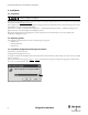
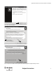
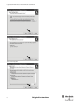
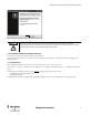
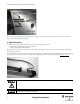
Table Of Contents
- Content
- 1. Introduction
- 2. Installation
- 3. Optical Interface
- 4. Configuration Tool for GuardShield Safe 2/Safe 4 Light Curtains
- 5. Configuration Tool for MSR42
- 5.1. Introduction
- 5.2. Starting MSR42 Configuration Tool
- 5.3. The menu bar
- 5.4. Main window
- 5.4.1. Tab “Design”
- 5.4.2. Tab “Diagnosis”
- 5.4.3. Tab “Application info”
- 5.4.4. Possible Configurations
- 5.4.5. Micro 400 Light Curtain
- 5.4.6. One Device (2 NC)
- 5.4.7. One or Two Device (OSSDs)
- 5.4.8. Safety override
- 5.4.9. Muting Micro 400
- 5.4.10. Muting other device (OSSDs)
- 5.4.11. Function “EDM” + “Start Release”
- 5.4.12. Function “Stop delay”
- 5.5. Download, Verify & Upload
- 5.6. Muting
- 5.6.1. General
- 5.6.2. Muting lamp
- 5.6.3. Muting sensors
- 5.6.4. Mute dependant override function
- 5.6.5. Sensor output delay function
- 5.6.6. Muting with enable signal
- 5.6.7. Muting disable function
- 5.6.8. Safety light curtain interruption monitoring function
- 5.6.9. 43BMuting time recorder
- 5.6.10. 44BSetup: 2 sensor T-type
- 5.6.11. Setup: four sensor T-type
- 5.6.12. Setup: two sensor L-type
- 5.6.13. Setup: two sensor T-type with enable signal
- 5.7. Blanking
- 6. Appendix

8
Light Curtain Multi-Function Control Module User Manual
Original instructions
Figure 9: Selection window
First select your preferred language with the pull-down option “Language” in the top right corner of the window. Then select your preferred sub
program and the safety warning window appears.
3. Optical Interface
The Optical Interface (Cat. Nr. 445L-AF6150) allows for a fast and easy communication between
• a GuardShield safety light curtain (Safe 2/Safe 4) and a PC or
• a safety controller module (MSR42) and a PC.
The Optical Interface can be used as a diagnosis tool (real time and long term diagnostics) in order to find errors such as insufficient supply voltage, a
short circuit of the output, etc.
The Optical Interface can also be used for down- and uploading configurations to a MSR42 controller. The MSR42 and Micro 400 features: blanking,
muting, override (and more) may be selected according to customer specific applications and downloaded as described in chapter 5 on page 13
.
Figure 10: Simple configuration with an Optical Interface
Access to the password, as well as the Optical Interface must only be permitted for authorized users.
Before connecting the USB Optical Interface to the computer the Configuration and Diagnostic Software has
to be installed (See chapter 2.3 on page 4)
.