MSR42, GuardShield Micro 400 and Safe 2/Safe 4 Light Curtains Configuration and Diagnostic Software Tool User Manual
Important User Information Because of the variety of uses for the products described in this publication, those responsible for the application and use of this control equipment must satisfy themselves that all necessary steps have been taken to assure that each application and use meets all performance and safety requirements, including any applicable laws, regulations, codes and standards.
Light Curtain Multi-Function Control Module User Manual I These products can only achieve their function as a safety controller module, if the instructions given in this instruction manual and the within mentioned documents are exactly followed, as well as consulting the valid laws and regulations at the time of installation. Should these instructions not be carefully followed, serious injury or death may occur.
Light Curtain Multi-Function Control Module User Manual Content Introduction . . . . . . . . . . . . . . . . . . . . . . . . . . . . . . . . . . . . . . . . . . . . . . . . . . . . . . . . . . . . . . . . . . . . . . . . . . . . . . . . . . . . . . . . . . . . . . . 2 Special Features . . . . . . . . . . . . . . . . . . . . . . . . . . . . . . . . . . . . . . . . . . . . . . . . . . . . . . . . . . . . . . . . . . . . . . . . . . . . . . . . . . . . . . . . . . . . . . . . . . . . . . . . . . . . . . . . .
Light Curtain Multi-Function Control Module User Manual Setup: two sensor L-type . . . . . . . . . . . . . . . . . . . . . . . . . . . . . . . . . . . . . . . . . . . . . . . . . . . . . . . . . . . . . . . . . . . . . . . . . . . . . . . . . . . . . . . . . . . . . . . . . . . . . . . . . . . . . Setup: two sensor T-type with enable signal . . . . . . . . . . . . . . . . . . . . . . . . . . . . . . . . . . . . . . . . . . . . . . . . . . . . . . . . . . . . . . . . . . . . . . . . . . . . . . . . . . . .
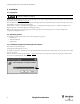
Light Curtain Multi-Function Control Module User Manual 2. Installation 2.1. Preparation Before connecting the USB optical interface to the computer, the software configuration tool has to be installed (See chapter 2.3 on page 4). During installation the USB driver software is copied to the hard drive. After this the USB Optical Interface can be connected to the computer and the driver software installed (See chapter 2.3 on page 4).
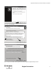
Light Curtain Multi-Function Control Module User Manual Figure 2: Welcome window for installation 1 2 Figure 3: License agreement Figure 4: Select target folder of installation.
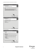
Light Curtain Multi-Function Control Module User Manual Figure 5: Select the start menu folder Figure 6: Create desktop symbol Figure 7: Run installation 6 Original instructions
Light Curtain Multi-Function Control Module User Manual Figure 8: Installation finished After installation, the authorized user is recommended to immediately enter their user registration information, as well as to change the password. The first time the program starts up, you will be automatically prompted to customize the password and user data. Access to the password, as well as the Optical Interface, must only be permitted for authorized personnel. 2.4.
Light Curtain Multi-Function Control Module User Manual Figure 9: Selection window First select your preferred language with the pull-down option “Language” in the top right corner of the window. Then select your preferred sub program and the safety warning window appears. 3. Optical Interface The Optical Interface (Cat. Nr. 445L-AF6150) allows for a fast and easy communication between • a GuardShield safety light curtain (Safe 2/Safe 4) and a PC or • a safety controller module (MSR42) and a PC.
Light Curtain Multi-Function Control Module User Manual The connection is simple and completed in seconds: • Plug the USB connector into an unused USB-port on your computer. • Press the suction cup of the sensor head onto the marked position. For a more secure connection, the suction cup may be dampened slightly. • Interrupt the light curtain (if connected). The communication between the Rockwell device and your computer will be initiated. 4.
Light Curtain Multi-Function Control Module User Manual The “system designer” is split into two sections, a “Designer’s Input” and “Designer’s Output” section. The “Designer’s input” section is used to define a light curtain: pair or transmitter or receiver, as well as the protective field height and resolution. The “Designers Output” section displays the resulting information and catalog number for the configured light curtain. To configure a light curtain stay in the Graphical Designer tab.
Light Curtain Multi-Function Control Module User Manual Response times Type of application Safety category Light curtain parameter Figure 14: Safety distance calculator To calculate the minimal safety distance, first answer the three application questions below: A “Industrial Application; Yes or No” Choose “Yes” if the application is industrial. Select “No” if the application is not industrial (this means that children also have access to the application).
Light Curtain Multi-Function Control Module User Manual Distance between light curtain pair Minimum reflective surface distance Figure 15: Safety distance example 4.3. Safe 2/Safe 4 Diagnostics Select the “diagnosis” tab in the Safe 2/Safe 4 configuration window. Figure 16: “Diagnosis” tab Connect the Optical Interface to your PC via the USB connector and attach the suction cup to the receiver of your Safe 2 or Safe 4 Light Curtain.
Light Curtain Multi-Function Control Module User Manual Figure 17: Safe 4 Diagnostics – Object blocking beams The “History” tab will allow the interrupted beams to be charted versus time. The “Service information” tab gives additional information for service / maintenance cases. The “Object height” tab gives information with regards to the height of objects which have interrupted the light curtain. 5. Configuration Tool for MSR42 5.1.
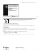
Light Curtain Multi-Function Control Module User Manual 2 1 Figure 19: “Welcome window” for MSR42. A “Warning: read safety information” symbol is shown on this welcome window. Click on this warning symbol (2) and read this safety information. By clicking on the “OK” Button (1) you accept this safety information, and the program will start. After installation, the authorized user is prompted to immediately enter their user registration information, as well as to change the password if desired.
Light Curtain Multi-Function Control Module User Manual 1 2 3 Figure 20: Main window with menu bar (1) and main tabs (2) as well as sub-tabs (3) 5.3. The menu bar The menu bar contains three pull-down menus: 1. File 2. Options 3. Help Figure 21: Items in the Menu bar 5.3.1. Menu “File” Menu “New” Create a new configuration. Menu “Open” Opens an existing configuration file according to the given String and Data name. “*.cfg” is defined as the standard extension for the configuration data name.
Light Curtain Multi-Function Control Module User Manual Menu “Configuration control document” Displays the current configuration control document on screen. Menu “Print configuration control document” Prints a Configuration Control Document with the current configuration. Menu “MSR42 Ö PC (Upload)” Uploads the current MSR42 control unit configuration into the PC (See chapter 5.5.4 on page 37).
Light Curtain Multi-Function Control Module User Manual Figure 23: Change password 5.3.2.3. Menu “Controller Description” The device number can be entered here or when downloading a configuration to a MSR42 controller (See chapter 5.5.1 on page 31). The field “Designation” can be used to name the configuration (Figure 24). This name will be printed on the configuration document (Figure 51). This name makes it easier to identify the configuration in the future. Figure 24: Controller description 5.3.2.4.
Light Curtain Multi-Function Control Module User Manual 5.3.3.3. Menu “Safety information” Gives important safety information for installing and operating the software. 5.3.3.4. Menu “About” Displays the welcome window to check software version. 5.4. Main window Three main tabs are available to choose from (Figure 20): 1. Design (See chapter 5.4.1 on page 18) 2. Diagnosis (See chapter 5.4.2 on page 21) 3. Application info (See chapter 5.4.3 on page 22) 5.4.1.
Light Curtain Multi-Function Control Module User Manual Detailed information on the various configurations are given in chapter 5.4.4 on page 23 4 1 2 3 Figure 25: Configuration window After selecting a component or a function, an individual specification window will pop up to allow further setting adjustments. Adjustments at a later point in time may also be made by clicking on the “Edit” button (4, Figure 25). All specification windows are set up similarly.
Light Curtain Multi-Function Control Module User Manual • Low Light Intensity (Micro 400) • Muting (Automatic) • Safety Override The info output is status information only. The output may not be used as a safety signal! C Safety Outputs OSSD Using the Edit button the following parameters may be selected. • Stop delay • External Device Monitoring In the lower portion of the Configuration window is a “System information” field, which gives information about design errors.
Light Curtain Multi-Function Control Module User Manual Figure 27: Basic configuration In this window eight different wiring options of the “Basic configuration” can be displayed. These options can be realized just by wiring any standard, out of the box MSR42 control unit (Cat. # 440R-P226AGS-NNR). No additional configuration is necessary. 5.4.2. Tab “Diagnosis” In order to carry out a diagnostic of a MSR42 control unit, the following steps must be made: 1.
Light Curtain Multi-Function Control Module User Manual 5.4.2.2. Service information For diagnosis of a MSR42 control unit, a short description of the error type may be found in the “Service Information” window (Figure 29). External and internal errors, as well as necessary corrective actions, will be displayed here. 1 2 Figure 29: Service information 5.4.3.
Light Curtain Multi-Function Control Module User Manual The machine stop time must also be entered. This “time” must consider the total length of time, from the moment the MSR45E expander relay contacts open (or when the OSSD outputs change from high to low), until the machine stops. The momentum of the machine, for example, must also be taken into consideration when calculating this stopping time.
Light Curtain Multi-Function Control Module User Manual Chapter Function. . . . . . . . . . . . . . . . . . . . . . . . . . . . . . . . . . . . . . . . . . . . . . . . . . . . . . . . . . . . . . . . Page 5.4.5 Micro 400 Light Curtain. . . . . . . . . . . . . . . . . . . . . . . . . . . . . . . . . . . . . . . . . . . . . . . . . . . . 35 5.4.5.1 5.4.5.2 5.4.5.3 Blanking . . . . . . . . . . . . . . . . . . . . . . . . . . . . . . . . . . . . . . . . . . . . . . . . . . . . . . . . . . . . . . . . . .
Light Curtain Multi-Function Control Module User Manual In the Micro 400 specification window it is also possible to specify the resolution and protective height of the Micro 400 light curtain attached to the MSR42 safety controller. When specified, the Micro 400 reaction time t(LC) will be calculated for this exact type of light curtain. This time is only valid if exactly this type of Micro 400 safety light curtain is connected to this MSR42 safety controller.
Light Curtain Multi-Function Control Module User Manual Figure 35: window "Interrupt Ignore time" Hint: The light curtain parameters: resolution and protective height must be defined before the interrupt ignore time function can be activated (support mode only) Important safety advice: • Interrupt Ignore Time will increase the response time. Recalculate the safety distance. 5.4.5.3.
Light Curtain Multi-Function Control Module User Manual Figure 36: Specification window “One Device (2 N.C.)” 5.4.7. One or Two Device (OSSDs) Figure 37: Specification window “One or Two Devices (OSSDs)” In order to configure an OSSD input device the specification window: “One/Two Device (OSSDs),” must be selected.
Light Curtain Multi-Function Control Module User Manual 5.4.8. Safety override Certain applications in practice require that the safety light curtain protective field needs to be overridden “manually” without the MSR42 safety contacts opening. A typical example of such an application is during the installation or service of a machine. It should be possible to run the machine even if the protective field is interrupted.
Light Curtain Multi-Function Control Module User Manual 5.4.8.2. Override One Device (OSSD) Figure 40: Specification window “Safety override” This function shows how to override a safety device with OSSD outputs (e.g GuardShield Safe 4). The MSR42 safety controller will be configured with Manual Start (Reset). Therefore for In1 or In2 the option ‘Start’ must be selected. One method can be selected to override an OSSD device: 1.
Light Curtain Multi-Function Control Module User Manual Figure 41: Specification window “Muting Micro 400” A detailed description of “Muting” is given in chapter 5.6 on page 37. 5.4.10. Muting other device (OSSDs) Figure 42: Specification window “Muting other device (OSSDs)” The MSR42 controller also offers the possibility of connecting one GuardShield safety light curtain or one laser scanner for muting applications.
Light Curtain Multi-Function Control Module User Manual 1 2 Figure 43: Stop delay setting and activating the function EDM or start release If the External Device Monitoring (EDM) field is chosen for external contactor monitoring (#2 in Figure 43), this function is active for both the safety outputs OSSD and extension relay module. The EDM function forces the safety outputs of the MSR42 control unit to open immediately if the monitored external N.C. circuit is not opened within 300 ms.
Light Curtain Multi-Function Control Module User Manual 1. Attach the Optical Interface to the MSR42 control module. 2. Disconnect the power supply to the MSR42 module. 3. Connect the Optical Interface to your PC. 4. Select menu item “File” – “PC -> MSR42 (Download).” 5. Enter the password and press “OK”-button (Figure 44). (to change the password see chapter 5.3.2.2 on page 16) Figure 44: Enter user password Using the unit protection key, see chapter 5.5.3 on page 35. 7.
Light Curtain Multi-Function Control Module User Manual Figure 46: Device no. printed on label The device number and designation must be entered. These inputs are later shown on the configuration control document and guarantees the product identification. 8. A window will appear, which shows the process of the communication from the PC to the MSR42 control module (Figure 47). 9. Now reconnect the +24V DC power supply to the MSR42 control module, and the data transmission will begin.
Light Curtain Multi-Function Control Module User Manual In case a MSR42 control unit is configured with a new configuration by an authorized person, the reaction times of the control unit may have changed. Therefore it is very important that after each configuration procedure: a. The new, valid configuration controldocument is printed-out (step 14) and put with the corresponding controller so that it is always present for maintenance and service purposes and b.
Light Curtain Multi-Function Control Module User Manual Figure 51: Configuration control document for MSR42 5.5.3. Configuration Protection The Unit Protection Key can be set to protect your MSR42 controller against unauthorized configuration changes. If set the configuration of the MSR42 can only be changed if the correct Unit Protection Key is entered. The key is set, if selected, while downloading the configuration into the MSR42 controller.
Light Curtain Multi-Function Control Module User Manual Store your Unit Protection Key safely and assure that only authorized personal have access to it. Without the Unit Protection Key, a protected MSR42 controller may not be reconfigured. It has to be replaced with a new control unit! Following the download procedure according chapter 5.5.
Light Curtain Multi-Function Control Module User Manual Figure 53: Wrong password message 5.5.4. MSR42 Ö PC (Upload) To review the configuration in a MSR42 control unit, the configuration data may be read out as follows: 1. Attach the Optical Interface to the controller 2. Disconnect the power supply to the MSR42 controller. 3. Connect the Optical Interface to the PC USB interface. 4. Select Menu item “MSR42 -> PC (Upload)” (#1 in Figure 21). 5.
Light Curtain Multi-Function Control Module User Manual 5.6.2. Muting lamp A muting lamp should be connected to warn an operator in the event that the light curtain is muted (see details in IEC 62046). The MSR42 may be configured to monitor a muting lamp. If it is configured with monitoring and the lamp is defective or not connected, the MSR will not initiate a muting condition, or will discontinue an existing muting condition.
Light Curtain Multi-Function Control Module User Manual It must be confirmed that the configuration of a muting sensor output delay does not have influence on the safety of the application. For example, the position of the muting sensors may have to be considered. 5.6.6. Muting with enable signal This function is only available for 2 sensor T-type with enable applications. In some applications muting should only be possible at certain times, for example only when a conveyor is running.
Light Curtain Multi-Function Control Module User Manual 5.6.9. 43BMuting time recorder The MSR42 offers the ability to configure many different timing sequences. During installation of a complete muting system it is often not clear what configured time values will guarantee trouble free operation. Small variations (e.g. in object size) may lead to unnecessary machine stoppage. To determine the timing of a given installation it is possible to measure the real timing sequence with the MSR42 control unit.
Light Curtain Multi-Function Control Module User Manual A detailed description about muting, muting restrictions as well as hints for the installation are given in the standard IEC 62046. Additional hints are mentioned in the attachment A7 of IEC 61496-1. Figure 57 shows the corresponding timing sequence for such an arrangement.
Light Curtain Multi-Function Control Module User Manual Figure 58: Configuration window for “Two sensor T-type” muting with 1 device (OSSD’s) safety device Figure 59 shows the wiring diagram for an example of a MSR42 control unit configured with the “two sensor, T-type” muting mode. For this muting mode two mute disable inputs may be configured. If selected, these signals must be “high” in order for a mute condition to take place (See chapter 5.6.7 on page 39).
Light Curtain Multi-Function Control Module User Manual Figure 60: Example, “four sensor (S1 - S4), T-type” muting This muting mode is similar to the “two sensor, T-type w/enable signal” muting (See chapter 5.6.6 on page 39), and should also be considered when the size and position of the pallet load is irregular, or the size of the pallet is much smaller than the width of the conveyor. Due to the two sensor input from either side of the light curtain, however an external enable signal (e.g.
Light Curtain Multi-Function Control Module User Manual Muting of the Micro 400 light curtain is achieved only when muting sensor S1 and S2 are activated within the specified time t(sens). For a successful muting sequence all four sensors must be simultaneously activated for a certain time period. The muting condition will stop when either sensor S3 or S4 is deactivated, or the maximal muting time t(mute) is exceeded (muting time out).
Light Curtain Multi-Function Control Module User Manual Figure 63: Example, “two sensor (S1 and S2) L-type” muting This muting mode is used to allow a load to exit a dangerous area while helping prevent access from outside the dangerous area. The object coming from the dangerous area interrupts the two muting sensors initiating the muting of the safety light curtain. As the object continues to move through the protective field muting remains active until the light curtain is no longer interrupted.
Light Curtain Multi-Function Control Module User Manual Parameter Default Value Max./Min. Values Possible Settings T(sens) [Figure 64] 2s Min.: 50 ms Max.: 10 s T(mute) [Figure 64] 5 min Min.: 0 ms Max.: 10 days (*) T(msdel) [5.6.5] 50 ms Min.: 0 ms Max.: 2.55 s N x 0.01 s Min.: N x 0.05 s Muting lamp monitoring [5.6.2] yes yes/no Mute dependant override [5.6.4] yes yes / no T(mdo) [5.6.4] 5s Mute disable signal [5.6.7] no Micro 400 interruption monitoring [5.6.
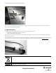
Light Curtain Multi-Function Control Module User Manual Figure 66: Wiring diagram “two sensor L-type” muting 5.6.13. Setup: two sensor T-type with enable signal Figure 67 shows a schematic arrangement for two sensor T-type with enable signal muting. Only the Micro 400 can be configured for two sensor T-type with enable signal muting. This version of muting is suited for applications when muting should only be possible at certain times; for example only when a conveyor is running.
Light Curtain Multi-Function Control Module User Manual A detailed description about muting, muting restrictions as well as hints for the installation are given in the standard IEC 62046. Additional hints are mentioned in the attachment A7 of IEC 61496-1. Figure 68 shows the corresponding timing sequence for such an arrangement.
Light Curtain Multi-Function Control Module User Manual Parameter Default Value Max./Min. Values Possible Settings T(sens) [Figure 68] 4s Min.: 50 ms Max.: 10 s N x 0.05 s T(mute) [Figure 68] 5 min Min.: 0 ms Max.: 10 days (*) T(msdel) [5.6.5] 50 ms Min.: 0 ms Max.: 2.55 s N x 0.01 s Muting lamp monitoring [5.6.2] yes yes/no Mute dependant override [5.6.4] yes yes / no T(mdo) [5.6.4] 5s Mute disable signal [5.6.7] no Micro 400 interruption monitoring [5.6.8] no T(espe) [5.6.
Light Curtain Multi-Function Control Module User Manual Figure 70: Wiring diagram for “two sensor T-type w/enable signal” muting 5.7. Blanking Generally, “Blanking” is understood to mean ignoring the interruption of specific beams within a light curtain. Certain applications cannot be protected in any other way.
Light Curtain Multi-Function Control Module User Manual Important safety notice: The operator must ensure that for all Blanking modes, no undetected access is possible into the danger zone via the "blanked" protective field throughout the whole width of the protective field (also left and right of the "blanked" object).
Light Curtain Multi-Function Control Module User Manual Important safety notice: Additionally, the blanked region should be clearly marked, and the protective field should be fully tested with the provided test rods according to the instructions given in the MSR42 user manual. The user should ensure that the number of blanked beams (i.e. the size of the object interrupting the protective field) will not be reduced during operation.
Light Curtain Multi-Function Control Module User Manual 5.7.4. Combining Blanking modes The protective field of a single Micro 400 light curtain may be split up and configured into different regions. From a safety technical point of view, it is especially critical that the resolution is inspected at the cross over point from one protective field region to the next, as well as the borders or edges of each region.
Light Curtain Multi-Function Control Module User Manual 1 2 3 Figure 73: Blanking window The first step is to define the resolution (1 Figure 73) and the number of beams or the protective field length of the Micro 400 light curtain (2). The length of the protective field as well as the physical resolution can be found on the specification label of the light curtain being configured.
Light Curtain Multi-Function Control Module User Manual In the case of "Fixed Blanking" (3 – Figure 74), the first (4) and last (5) interrupted beams must be defined and thereafter confirmed with a cursor click on the "Quick check" box (7). Floating Blanking 1 2 4 5 8 3 6 7 9 Figure 75: Floating Blanking window In the case of "Floating Blanking" (3 – Figure 75), the area in which the object is allowed to move must first be defined (4 and 5).
Light Curtain Multi-Function Control Module User Manual 56 Original instructions
Technical Support / Technische Unterstützung / Assistance technique / Assistenza tecnica / Asistencia técnica ENGLISH DEUTSCH FRANÇAIS ITALIANO ESPAÑOL PORTUGUÊS POLSKI ČESKY SVENSKA NEDERLANDS Installation of this product must not take place until the installer has obtained a copy of the manufacturer’s instructions in a language which he can understand. This instruction sheet is available in multiple languages at http://rockwellautomation.com/literature.
GuardShield is a trademark of Rockwell Automation, Inc. Guardmaster is a registered trademark of Rockwell Automation, Inc. www.rockwellautomation.com Power, Control and Information Solutions Headquarters Americas: Rockwell Automation, 1201 South Second Street, Milwaukee, WI 53204 USA, Tel: (1) 414.382.2000, Fax: (1) 414.382.