
Owner's manual

MSR04X
I
October
200
5
–
Issue 8
7
Triguard
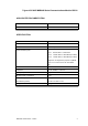
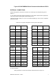
SC300E MSR04XI Serial Communications Module RS232
Port
1
(9
-
way)
J2
(backplane)
1
n/c
2
Rx
A12
3 Tx
C10
4
n/c
5 Ground
A14
6
n/c
n/c
7 RTS
A10
8 CTS
C12
9
n/c
n/c
Port
3
(9
-
way)
J2
(backpl
ane)
1
n/c
2
Rx
A28
3 Tx
C26
4
n/c
5 Ground
A30
6
n/c
n/c
7 RTS
A26
8 CTS
C28
9
n/c
n/c
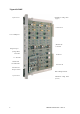
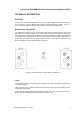
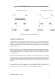
EXTERNAL
CONNECTIONS
Pinouts
and
signals
for
front
panel
connectors
J4
to
J6
through
to
J2
backplane
are
given
in
Table
2
-
2.
Is
your
interface
DTE
(data
terminal
equipment)
or
DCE
(data
communications
equipment)?:
The
point
of
reference
for
all
signals
is
the
terminal
(or
PC).
Transmit
and
receive
leads
(2
or
3)
can
be
reversed
depending
on
the
use
of
the
equipment,
either
DTE
or
DCE.
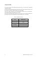
Table
2
-
2.
Front
panel
& backplane
connector
pinouts
with
signals
Port
0
(9
-
way)
J2
(backplane
1
n/c
2
Rx
A4
3 Tx
C2
4
n/c
5 Ground
A6
6
n/c
n/c
7 RTS
A2
8 CTS
C4
9
n/c
n/c
Port
2
(9
-
way)
J2
(backplane)
1
n/c
2
Rx
A20
3 Tx
C18
4
n/c
5 Ground
A22
6
n/c
n/c
7 RTS
A18
8 CTS
C20
9
n/c
n/c
n/c
=No
connection
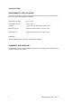
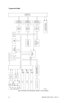
Wiring
schematic
for
serial
communication
cables
are
shown
in
Figure
2
-
2
.