
Owner's manual

6
MSR04X
I
October
200
5
–
Issue 8
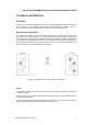
Triguard
SC300E
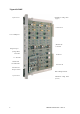
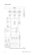
On
the
lower
section
of
the
PCB
are
three
further
links,
LK2,
LK3
and
LK4,
located
and
configured
as
follows:
LK2
(2
-
pin)
located
approximately
220mm
down
from
the
top
of
the
module
and
110mm
in
from
the
front
face,
used
in
the
voltage
monitoring
circuit,
always
fitted.
LK3
(3
-
pin)
located
beneath
the
plug
in
daughterboard.
Used
for
3
-
2
-
1
-
or
3
-
2
-
0 operation,
factory
fitted
hard
wired,
all
pins
linked
for
3
-
2
-
1 mode.
LK4
(3
-
pin)
located
approximately
250mm
down
from
the
top
of
the
module
and
220mm
from
the
front
face,
used
for
the
daughterboard
clock
speed
setting,
pins
1 and
2 linked.
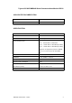
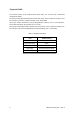
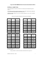
Table
2
-
1.
Default
link
settings
Link
Default
setting
LK1
(3
off
x 3 pin)
Links
not
fitted
LK2
(3
off
x 8 pin)
Fitted
LK2
(2
pin)
Fitted
LK3
(3
pin)
Hard
wired
(all
pins
linked)
LK4
(3
pin)
Fitted
(pins
1 & 2 link
ed)