Triguard SC300E MSR04XI Serial Communications Module RS232 (MSR04XI) Issue 8 October 2005 INTRODUCTION AND TECHNICAL DATA PURPOSE The Serial Communications Module provides a serial interface between the SC300E environment and a variety of remote devices complying with the standard RS232-C. At least one Serial Communications Module must be used in the system and fitted in Slot 10 of the main chassis to enable communications between the system processors and the workstations.
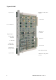
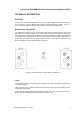
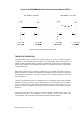
Triguard SC300E Ejector lever Mechanical coding block (Upper) Connector J1 User COMM ports (Module ID) Link LK2 Diagnosticport (Voltage Mon) Link LK2 Link LK4 Tx / Rx LEDs Health LED ON/OFF LEDs Connector J2 ON/OFF Line Request switch RS232 Daughterboard Ejector lever 2 Mechanical coding block (Lower) MSR04XI October 2005 – Issue 8
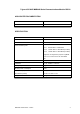
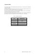
Triguard SC300E MSR04XI Serial Communications Module RS232 ASSOCIATED DOCUMENTATION Reference No 008-5097 Title Chassis User Manual SPECIFICATION Model MSR04XI Communications Serial RS232 Mictrocontroller Intel family Communication ports: Port 0: RS232 9600 or 19200 Baud Port 1: RS232 9600 or 19200 Baud Port 2: RS232 9600 or 19200 Baud (see Note) Port 3: RS232 9600 or 19200 Baud (see Note) Diagnostic: for diagnostics purposes only Note: Ports 2 & 3 must be set to the same Baud rate.
Triguard SC300E ENVIRONMENTAL SPECIFICATIONS The maximum ambient temperature measured at the hottest point within the Triguard system shall not be greater than 60 degrees centigrade. Temperature operating: +5°C to +60°C Temperature storage: -25°C to +70°C Humidity 5% to 95% non-condensing at ambient <40°C EMC/RFI Immunity Tested and certified to IEC 1131-Part 2 1994 Vibration/Shock Tested and certified to IEC 1131-Part 2 1994 Certification: General Certification: Ref.
Triguard SC300E MSR04XI Serial Communications Module RS232 TECHNICAL DESCRIPTION PHYSICAL The Serial Communications Module is a 9U high PCB with integral front panel and front and rear connectors; a plug-in daughter board carries the RS232 interface circuits. Figure 1-1 shows the general layout, location of the connectors and front panel components.
Triguard SC300E On the lower section of the PCB are three further links, LK2, LK3 and LK4, located and configured as follows: LK2 (2-pin) located approximately 220mm down from the top of the module and 110mm in from the front face, used in the voltage monitoring circuit, always fitted. LK3 (3 -pin) located beneath the plug in daughterboard. Used for 3-2-1-o r 3-2-0 operation, factory fitted hard wired, all pins linked for 3-2-1 mode.
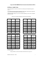
Triguard SC300E MSR04XI Serial Communications Module RS232 EXTERNAL CONNECTIONS Pinouts and signals for front panel connectors J4 to J6 through to J2 backplane are given in Table 2-2. Is your interface DTE (data terminal equipment) or DCE (data communications equipment)?: The point of reference for all signals is the terminal (or PC). Transmit and receive leads (2 or 3) can be reversed depending on the use of the equipment, either DTE or DCE. Table 2-2.
Triguard SC300E 8 MSR04XI October 2005 – Issue 8
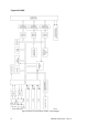
Triguard SC300E MSR04XI Serial Communications Module RS232 Figure 2-2 Serial communications cable wiring THEORY OF OPERATION Triplicated data enters and leaves the module (Figure 2-3 ) via the chassis backplane connector J1 and is isolated from the MPP by bus transceivers. Data for transmission is loaded into dual port RAM in each of the three circuit branches and is voted 2-oo-3 before being passed to the USARTs on the daughter board where it is serialised and sent to the appropriate communications port.
Triguard SC300E Figure 2-3 Serial communications module – Block diagram 10 MSR04XI October 2005 – Issue 8
Triguard SC300E MSR04XI Serial Communications Module RS232 SERVICING SCOPE CAUTION: 1 The module contains components that may be electrostatically sensitive, it should be transported and stored in its original packaging material. System repair is by module replacement. Faulty modules are not repairable in the field; they should be returned for repair. DIAGNOSIS The TriBuild workstation is used for fault diagnosis.
Triguard SC300E Operate the On/off Line Request switch and check that the three On Line LEDs illuminate for one second, extinguish for one second and then illuminate permanently to indicate that the module has been put on-line. If the LEDs do not illuminate either the first or second time or fail to remain illuminated, then the module must be considered faulty. PREVENTIVE MAINTENANCE No preventive maintenance is necessary.
Triguard SC300E MSR04XI Serial Communications Module RS232 SERVICE SUPPORT SPARE PARTS Spare parts and technical advice can be obtained from your local area office.