
Instruction Manual
4
MRB04XM
October
200
5
–
Issue 5
Triguard
SC300E
TECHNICAL
DESCRIPTIO
N
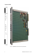
PHYSICAL
Th
e MRB04XM
Remote
Bus
Extender
Master
Module
is
a 9U
high
PCB
with
integral
front
panel.
A general
view
of
the
main
components
is
shown
in
Figure
2
-
1 . DIP
switches
SW1
and
SW2
are
used
to
set
the
enable
and
addresses
of
up
to
four
remote
chassis.
EXTERNAL CONNECTIONS
Each
module
is
plugged
into
an
extension
chassis
backplane
bus
system
via
two
DIN41612
connectors
J1
and
J2
(Figure
2
-
1 ).
The
connections
to
remote
chassis
are
serial
links
along
fibre
-
optic
cables
which
plug
into
ST
type
transmitter
and
receiver
connections
on
the
front
panel.
The
top
four
connectors
are
the
transmitters
and
the
lower
four
are
receivers
enabling
two
-
way
communication
between
the
master
modules
and
up
to
four
slave
modules
in
remote
chassis.
CHASSIS BACKPLANE
The
signals
passin
g through
J1
and
J2
are
available
at
the
rear
of
the
extension
chassis
backplane.
The
rear
backplane
connectors
are
shown
in
Figure
2
-
6
.
For
additional
information,
refer
to
the
Chassis
user
manual
(Ref
008
-
5097).
Connector
J1
links
the
Remote
Bus
Extender
to
the
I/O
modules
in
the
local
chassis.
Extensions
are
provided
to
the
pins
of
the
J1
mating
connector
(96
pins
in
three
columns
‘a’,
‘b’
and
‘c’).
Pins
07
to
10
of
columns
‘b’
and
‘c’
are
specially
extended
to
enable
the
installation
of
the
chassis
ad
dress
setting
links
(see
Figure
2
-
6
).
The
I/O
modules
interface
to
three
isolated
communications
buses
(shown
collectively
as
the
‘I/O
Bus’
in
Figure
2
-
5 ),
each
bus
being
served
by
one
of
the
Remote
Bus
Extenders.
Columns
‘a’
and
‘c’
of
connectors
J2
link
each
Remote
Bus
Extender
to
the
expansion
bus
via
rear
backplane
connectors
‘e’.
The
same
basic
chassis
is
used
for
the
main
chassis,
the
extension
chassis
and
the
remote
chassis.
The
following
chassis
backplane
features
are
not
used
in
the
extension
c
hassis
application
at
this
time:/
1.
The
inter
-
processor
communications
bus
(Figure
2
-
5 ) and
hence
Column
‘b’
of
connector
J2/backplane
connector
‘e’
2.
Watchdog
timer
‘WDT’
connectors
‘f’
(Figure
2
-
6 )
3.
Di
agnostic
serial
ports
‘g’
(Figure
2
-
6
).