
Owner manual

6
MRB01X
S
Octob
er
2005
–
Issue 4
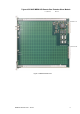
Trigua
rd
SC300E
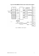
EXPANSION BUS
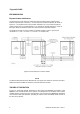
Expansion bus architecture
The
main
and
any
local
extension
chassis
are
interconnected
by
ribbon
cables
running
between
expansion
bus
connectors
‘e’
on
their
respective
chassis
backplanes
as
shown
in
Figure
2
-
2
.
The
expansion
bus
may
be
further
extended
to
up
to
four
remote
chassis
per
master
module
(up
to
an
overall
maximum
of
15
chassis
per
SC300E
system)
by
means
of
fibre
-
optic
cables
terminated
at
master
and
slave
remote
bus
extender
modules.
The
maximum
number
of
remote
chassis
per
SC300E
system
is
eleven—given
by
the
combination:
1 x main
+ 3 x local
+ 11
x remote
= 15
chassis
total.
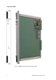
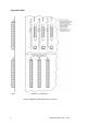
Figure
2
-
2 Bus
extension
to
remote
chassis
NOTE
The
Remote
Bus
Extender
Slave
Modules
will
only
support
the
chassis
in
which
they
are
fitted.
Additional
chassis
CANNOT
be
added
to
a Remote
Extension
Chassis.
THEORY OF OPERATION
Figure
2
-
2 shows
the
general
architecture
of
the
system
and
identifies
the
position
of
the
MRB01X
S.
The
overall
function
of
the
system
is
to
interface
the
I/O
modules
of
the
remote
chassis
with
the
processors
in
the
main
chassis.
At
a local
level,
the
MRB01XS
terminates
one
end
of
the
fibre
optic
data
link,
operating
as
a slave
to
the
associated
maste
r module
at
the
other
end
of
the
link.