
Owner manual

4
MRB01X
S
Octob
er
2005
–
Issue 4
Trigua
rd
SC300E
TECHNICAL
DESCRIPTIO
N
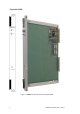
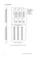
PHYSICAL
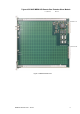
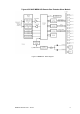
The
MRB01XS
Remote
Bus
Extender
Slave
Module
is
a 9U
high
PCB
with
integral
front
panel.
A general vie
w of
the
main
components
is
shown
in
Figure
2
-
1
.
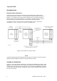
EXTERNAL
CONNECTIONS
The
MRB01XS
is
plugged
into
the
remote
chassis
backplane
bus
system
via
two
DIN41612
connectors
J1
and
J2.
Connections
to
the
associated
master
module
are
via
fibre
-
optic
cables
which
plug
into
transmitter
and
receiver
connections
on
the
front
panel.
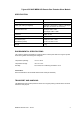
CONNECTOR SUMMARY
Table
2
-
1.
Connector
summary
Connector
Location
Type
J1
(I/O
bus)
Rear
edge
of
MRB01XS
(Figure 2
-
1 )
96
-
pin
DIN41612
type
C male
J2
(expansion
bus)
Rear
edge
of
MRB0
1XS
(Figure 2
-
1 )
96
-
pin
DIN41612
type
C male
Transmit
(Tx)
and
Receive (Rx)
MRB01XS
front
panel
ST
Connected
by
62.5/125
m
multimode
cable
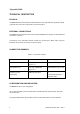
CONFIGURATION AND INDICATORS
The
MRB01XS
has
no
user
configuration.
The
Tx
and
Rx
LEDS
on
the
front
panel
flash
to
indicate
that
their
respective
fibre
optic
links
are
passing
data.
The
single
Health
indicator
(green
LED)
on
the
fron
t
panel
illuminates
in
normal
operation
.