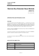
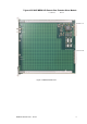
Triguard SC300E MRB01XS Remote Bus Extender Slave Module (MRB01XS) Issue 4 October 2005 INTRODUCTION AND TECHNICAL DATA PURPOSE A Remote Bus Extender Slave Module MRB01XS (Figure 1-1 ) is located in each of the three right-hand slots (A, B and C) of a remote extension chassis. Fibre optic cables link each MRB01XS to a corresponding master module (MRB04XM) in a local extension chassis.
Triguard SC300E Figure 1-1 MRB01XS General view and front panel detail 2 MRB01XS October 2005 – Issue 4
Triguard SC300E MRB01XS Remote Bus Extender Slave Module SPECIFICATION Model MRB01XS Fibre optic ports 1 transmit, 1 receive Fibre optic cable (not supplied) Multimode 62.5/125;m cable & 50/125;m cable (ST connector to ST connector) Maximum drive loss 50/125;m cable = 9dB 62.5/125;m cable = 16dB Indicators Health, Tx, Rx Module power consumptin 3W Overall size (mm) 400(9U)H x 397L x 28W Overall size (inches) 15.75H x 15.63L x 1.1W Weight 1.
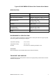
Triguard SC300E TECHNICAL DESCRIPTION PHYSICAL The MRB01XS Remote Bus Extender Slave Module is a 9U high PCB with integral front panel. A general view of the main components is shown in Figure 2-1 . EXTERNAL CONNECTIONS The MRB01XS is plugged into the remote chassis backplane bus system via two DIN41612 connectors J1 and J2. Connections to the associated master module are via fibre-optic cables which plug into transmitter and receiver connections on the front panel. CONNECTOR SUMMARY Table 2-1.
Triguard SC300E MRB01XS Remote Bus Extender Slave Module U3 (FPGA) Fuse F1 Connector J1 Connector J2 Figure 2-1 MRB01XS Side view MRB01XS October 2005 – Issue 4 5
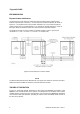
Triguard SC300E EXPANSION BUS Expansion bus architecture The main and any local extension chassis are interconnected by ribbon cables running between expansion bus connectors ‘e’ on their respective chassis backplanes as shown in Figure 2-2 . The expansion bus may be further extended to up to four remote chassis per master module (up to an overall maximum of 15 chassis per SC300E system) by means of fibre-optic cables terminated at master and slave remote bus extender modules.
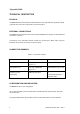
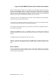
Triguard SC300E MRB01XS Remote Bus Extender Slave Module Remote chassis address selection is controlled from the associated remote bus extender master module MRB04XM. Refer to the Remote Bus Extender Master Module User Manual (Ref 008-5117) for details. There are no address setting links or switches on the MRB01XS itself. The chassis address setting links ‘UNIT ID 0 to 3’ at the rear of the remote chassis backplane are not used. Links fitted in these positions will have no effect.
Triguard SC300E 0 1 2 3 UNIT ID 0 1 2 3 UNIT ID 0 1 2 3 UNIT ID Figure 2-3 MRB01XS - Related backplane connectors 8 MRB01XS October 2005 – Issue 4
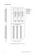
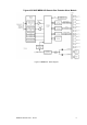
Triguard SC300E MRB01XS Remote Bus Extender Slave Module Figure 2-4 MRB01XS - Block diagram MRB01XS October 2005 – Issue 4 9
Triguard SC300E SERVICING SCOPE The MRB01XS is not field repairable. Field servicing operations are confined to the total replacement of faulty MRB01XS. Return the faulty MRB01XS for repair. DIAGNOSIS A faulty MRB01XS will be apparent by a single I/O channel failure affecting all the field devices serviced by a particular remote chassis. The Health LED may also be extinguished CONFIGURATION There are no configurable links or switches.
Triguard SC300E MRB01XS Remote Bus Extender Slave Module SERVICE SUPPORT SPARE PARTS Spare parts and technical advice can be obtained from your local area offices.