Installation Instructions MP-Series Stainless Steel Servo Motor with 100 mm to 165 mm Frame Size Catalog Numbers MPS-A330, MPS-A4540, MPS-B330, MPS-B4540, MPS-B560 Topic Page Important User Information 2 Catalog Number Explanation 3 About the MP-Series Stainless Steel Servo Motor 4 Before You Begin 4 Install the Motor 9 Product Dimensions 12 Motor Load Force Ratings 14 Connector Data 15 Remove and Install a Shaft Key 18 Slinger and Shaft Seal Removal and Installation 19 Motor Cables a
MP-Series Stainless Steel Servo Motor with 100 mm to 165 mm Frame Size Important User Information Read this document and the documents listed in the additional resources section about installation, configuration, and operation of this equipment before you install, configure, operate, or maintain this product. Users are required to familiarize themselves with installation and wiring instructions in addition to requirements of all applicable codes, laws, and standards.
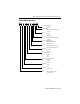
MP-Series Stainless Steel Servo Motor with 100 mm to 165 mm Frame Size 3 Catalog Number Explanation MP S - x x x x x - x J 5 x D A Factory Designated Options A = Standard Mounting Flange D = IEC metric, tapped mounting holes (type FT) Brake 2 = No brake 4 = 24V DC brake Connectors 5 = Cables with circular DIN (SpeedTec) connectors Enclosure/Shaft Key/Shaft Seal J = IP66/IP67/IP69K housing/ shaft key/shaft seal Feedback M = Multi-turn high-resolution encoder S = Single-turn high-resolution encoder Rated Spe
MP-Series Stainless Steel Servo Motor with 100 mm to 165 mm Frame Size About the MP-Series Stainless Steel Servo Motor The MP-Series™ stainless steel (Bulletin MPS) motors are designed to meet the unique needs of hygienic manufacturing environments such as food, beverage, brewing, dairy, health and beauty, and pharmaceutical products. Before You Begin Remove all packing material from within and around the item. After unpacking, verify the nameplate catalog number against the purchase order. 1.
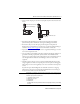
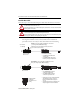
MP-Series Stainless Steel Servo Motor with 100 mm to 165 mm Frame Size 5 • Always provide a drip loop in each cable to carry liquids away from the connection to the motor. The cable enters above the motor and does not form a drip loop. The cable enters beneath the motor and forms a drip loop. • If possible, provide shields that protect the motor housing, shaft seals, and their junctions from product contamination, caustic agents, and high pressure fluids.
MP-Series Stainless Steel Servo Motor with 100 mm to 165 mm Frame Size Using Shaft Seals An additional seal is required on the motor shaft near the motor front bearing, if the shaft is exposed to fluids or significant amounts of fine dust. This includes lubricating oil from a gearbox. An IP66, IP67, or IP69K rating for the motor requires the use of a shaft seal and environmentally sealed connectors/cables.
MP-Series Stainless Steel Servo Motor with 100 mm to 165 mm Frame Size 7 Preventing Electrical Noise Electromagnetic interference (EMI), commonly called noise, can adversely impact motor performance by inducing stray signals. Follow these guidelines to prevent the effects of EMI: • Isolate the power transformers, or install line filters on all AC input power lines. • Separate signal cables from motor cabling and power wiring.
MP-Series Stainless Steel Servo Motor with 100 mm to 165 mm Frame Size Power Cable Shielding Power cables must be shielded, and the cable shield connects to ground. ATTENTION: High voltage can be present on the shields of a power cable, if the shields are not grounded. Verify there is a connection to ground for all shields in the power cable.
MP-Series Stainless Steel Servo Motor with 100 mm to 165 mm Frame Size 9 Install the Motor MP-Series motors include a mounting pilot for aligning the motor on the machine. Preferred fasteners are stainless steel. The installation must comply with all local regulations and use equipment and installation practices that promote safety and electromagnetic compatibility. ATTENTION: Unmounted motors, disconnected mechanical couplings, loose shaft keys, and disconnected cables are dangerous if power is applied.
MP-Series Stainless Steel Servo Motor with 100 mm to 165 mm Frame Size Attach the Motor Cables Follow these steps to attach the feedback and power/brake cables after the motor is mounted. ATTENTION: Servo drive power must be turned off before connecting or disconnecting the cables to the motor, and if a cable is left disconnected at the motor end. Arcing or unexpected motion can occur if the feedback, power, or brake cables are connected or disconnected while power is applied to the servo drive.
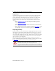
MP-Series Stainless Steel Servo Motor with 100 mm to 165 mm Frame Size 11 2. Form a drip loop in the cable (see page 5). 3. Carefully align the flat surface on the feedback or the power/brake cable plug (shown in the diagram) with the flat surface on the motor connector. Power and Brake Plug Feedback Plug Align flat surfaces with logo on top. Align flat surfaces with logo on top. 4.
MP-Series Stainless Steel Servo Motor with 100 mm to 165 mm Frame Size Product Dimensions This section provides dimensions for the motors. L P LB S (dia. hole) on M (bolt circle) L-LB T HD CAB DB E Removable Plug for Optional Air Pressurization Kit D N See Detail A CAR (cable bend radius) Feedback Connector Power and Brake Connector LE Detail A Flush to Pilot Flush to Shaft GE F Shaft Seal Shaft End Threaded Hole: MPL-x330 - M5 x 0.8 Thread Depth 12.5 mm (0.49 in.) MPL-x4540 - M8 x 1.
MP-Series Stainless Steel Servo Motor with 100 mm to 165 mm Frame Size 13 These dimensions are for non-brake motors with a single-turn encoder. Footnotes provide the additional dimensions for the brake options, and the tolerances for common dimensions. Dimensions Motor Cat. No. D (1) DB E HD L (2), (3) L-LB (2), (3) LB LE (4) M mm (in.) mm (in.) mm (in.) mm (in.) mm (in.) mm (in.) mm (in.) mm (in.) mm (in.) MPS-A/B330 16.0 (0.63) 50.8 (2.0) 32.13 (1.26) 135.0 (5.31) 230.0 (9.
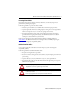
MP-Series Stainless Steel Servo Motor with 100 mm to 165 mm Frame Size Motor Load Force Ratings Motors can operate with a sustained shaft load. The figure shows radial and axial load force locations, and the tables provide maximum values for each force. Load Forces on Motor Shaft Radial Load Force is applied at center of shaft extension. Axial Load Force The tables represent 20,000 hour L10 bearing fatigue life at various loads and speeds.
MP-Series Stainless Steel Servo Motor with 100 mm to 165 mm Frame Size 15 Connector Data This table provides the signal descriptions for the feedback, power, and brake pinouts on the connectors.
MP-Series Stainless Steel Servo Motor with 100 mm to 165 mm Frame Size Motor Cables Use these figures to identify the cable wiring for 230V motors (catalog number MPS-Axxx) or 460V motors (catalog number MPS-Bxxx). This figure depicts the wiring of a power and brake cable for a 230V or 460V motor.
MP-Series Stainless Steel Servo Motor with 100 mm to 165 mm Frame Size 17 Feedback Cable Schematics 1 2 3 4 5 6 9 10 11 12 13 14 15 16 17 7 8 SIN+ SINCOS+ COSDATA+ DATAEPWR 5V ECOM N/C N/C TS+ TSN/C N/C N/C N/C N/C N/C N/C N/C N/C N/C N/C 28 AWG Black 28 AWG White/Black 28 AWG Red 28 AWG White/Red 28 AWG Green 28 AWG White/Green 16 AWG Grey 16 AWG White/Grey 22 AWG Orange 22 AWG White/Orange 28 AWG Blue 28 AWG White/Blue 28 AWG Yellow 28 AWG White/Yellow 28 AWG Brown 28 AWG White/Brown 28 AWG 28 AWG 2
MP-Series Stainless Steel Servo Motor with 100 mm to 165 mm Frame Size Remove and Install a Shaft Key Shaft keys for the Bulletin MPS motors are constructed of stainless steel - 300 series. The specified tolerance provides an interference fit (slightly larger than the opening) for a secure and rigid connection. ATTENTION: Do not strike the motor’s shaft, couplings, or pulleys with tools during installation or removal of the shaft key.
MP-Series Stainless Steel Servo Motor with 100 mm to 165 mm Frame Size 19 Slinger and Shaft Seal Removal and Installation The slinger and a shaft seal provide environmental sealing for Bulletin MPS motors. The slinger shields the shaft seal from contact with the full force of high-pressure cleaning fluids, while the shaft seal provides a secondary barrier to moisture and particle intrusion that protects the motor bearings.
MP-Series Stainless Steel Servo Motor with 100 mm to 165 mm Frame Size Remove the Shaft Seal The shaft seal can be safely removed by partially inserting an appropriately sized screw or bolt into the face of the shaft seal. The head of the screw or bolt provides a convenient point to grasp and remove the shaft seal. Before installing the screw, create a pilot hole appropriate for the screw being used. Use masking tape or a depth sleeve to establish a drilling depth limit of 4 mm (0.16 in.
MP-Series Stainless Steel Servo Motor with 100 mm to 165 mm Frame Size 21 Install the Replacement Slinger 1. Install a threaded rod and nut in the shaft alignment hole. The table below lists the diameter and threading of alignment holes, and a recommended rod length for each motor. Hex Nut and Threaded Rod Sizing Motor Cat No. MPS-x330 Threaded Shaft Threaded Rod Size with Recommended Length mm (in.) M5 x 0.8 thread size x 175 (6.9) MPS-x4540 M8 x 1.25 thread size x 200 (7.9) MPS-x560 M10 x 1.
MP-Series Stainless Steel Servo Motor with 100 mm to 165 mm Frame Size Adjust the Clearance between the Slinger and Motor Face 1. Position two 0.5 mm (0.02 in.) feeler gauges between the motor face and slinger: one feeler gauge on each side of the shaft. 2. Slowly tighten or back-off the nut to adjust the slinger on the shaft. Adjustment is complete when the slinger lightly and evenly contacts both feeler gauges. TIP Replace the shaft key, if the motor is so equipped, after removing all tools.
MP-Series Stainless Steel Servo Motor with 100 mm to 165 mm Frame Size 23 Sealing Air Accessory Kit A sealing air pressure kit (catalog number MPS-AIR-PURGE) is available for field installation on Bulletin MPS motors. The kit provides a quick-release female air fitting. Positive air pressure applied to the motor provides an additional level of protection against the ingress of foreign substances and moisture.
MP-Series Stainless Steel Servo Motor with 100 mm to 165 mm Frame Size Specifications The exterior surfaces of the MP-Series stainless steel servo motors are made from the materials in the table. Store the motor in a clean and dry location within the environmental conditions.
MP-Series Stainless Steel Servo Motor with 100 mm to 165 mm Frame Size 25 Additional Resources These documents contain additional information concerning related products from Rockwell Automation.
Rockwell Automation Support Rockwell Automation provides technical information on the Web to assist you in using its products. At http://www.rockwellautomation.com/support you can find technical and application notes, sample code, and links to software service packs. You can also visit our Support Center at https://rockwellautomation.custhelp.com/ for software updates, support chats and forums, technical information, FAQs, and to sign up for product notification updates.